The open source world and Chinese manufacturing have a long relationship. Some fifteen years ago, the big topic was how companies could open-source their hardware designs and not get driven bankrupt by competition from overseas. Companies like Sparkfun, Adafruit, Arduino, Maple Labs, Pololu, and many more demonstrated that this wasn’t impossible after all.
Maybe ten years ago, Chinese firms started picking up interesting hacker projects and producing them. This gave us hits like the AVR transistor tester and the NanoVNA. In the last few years, we’ve seen open-source hardware and software projects that have deliberately targeted Chinese manufacturers, and won. We do the design and coding, they do the manufacturing, sales, and distribution.
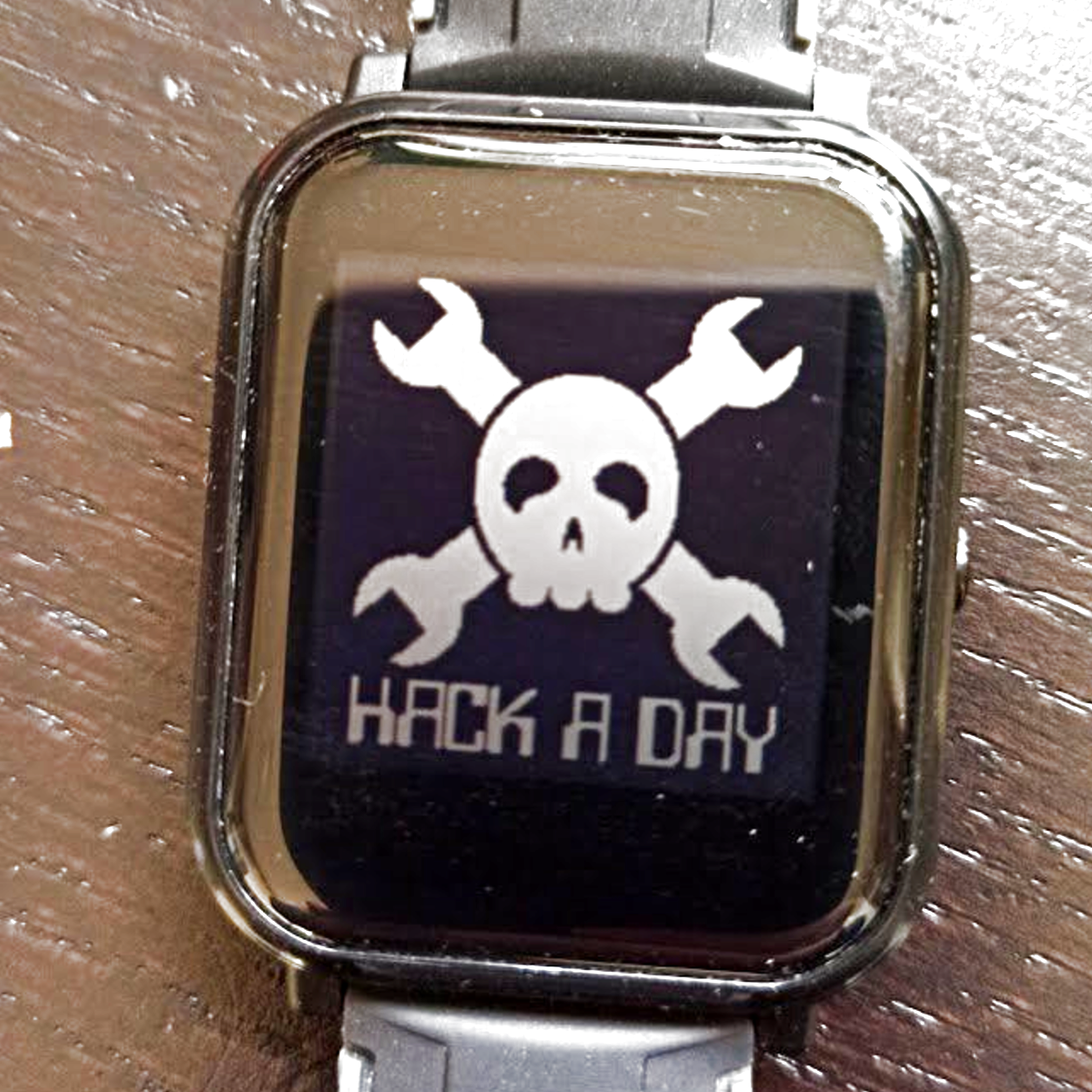 But this is something else: the Bangle.js watch takes an essentially mediocre Chinese smartwatch and reflashes the firmware, and sells them as open-source smartwatches to the general public. These pre-hacked watches are being sold on Kickstarter, and although the works stands on the shoulders of previous hacker’s reverse engineering work on the non-open watch hardware, it’s being sold by the prime mover behind the Espruino JavaScript-on-embedded language, which it runs on.
We have a cheap commodity smartwatch, being sold with frankly mediocre firmware, taken over by hackers, re-flashed, re-branded, and sold by the hackers on Kickstarter. As a result of it being (forcibly) opened, there’s a decently sized app store of contributed open-source applications that’ll run on the platform, making it significantly more useful and hacker friendly than it was before.
Will this boost sales? Will China notice the hackers’ work? Will this, and similar projects, end up in yet another new hacker/China relationship? We’re watching.