Add Some LED Enhancement To Your Netbook Lid

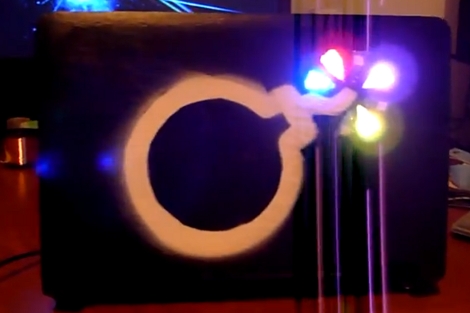
[Mathieu] needed to open up his Acer Aspire One to do a hard drive replacement and decided to add a bit of pizzazz while he was in there. The image above is the lid of the netbook adorned with RGB LEDs and a spray painted stencil.

He previously purchased a set of surface mount RGB packages on eBay and thought that they were perfect for this hack. after removing the case he found that by using a flex PCB he would be able to fit the LEDs inside, and pass the connections through to the main computer housing. The leads connect to a Teensy board, which is held in place with a liberal application of hot glue. [Mathieu] removed the USB connector and soldered jumper wires to one of the computers ports. In the video after the break you can see that he uses the programming software to write some code to the Teensy, driving the LEDs. We’d like to see it set to listen for serial communications and react accordingly. That way you could use it for notifications, as an audio VU meter, to track torrent progress, etc.

Continue reading “Add Some LED Enhancement To Your Netbook Lid”

Beginner Concepts: A Quartet Of Videos On Inductors

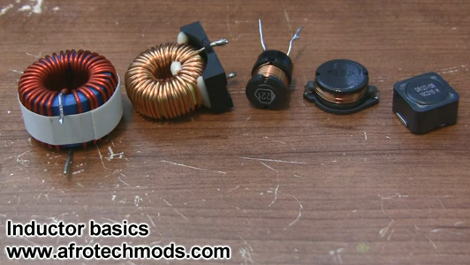
Inductors can be found in many of the devices you use every day, but if you’ve been working only with DC in your projects there’s a good chance you’ve never needed to know anything about them. Now’s your chance to pick up on the basics with this video tutorial series. [Afroman] put together four short videos that we’ve embedded after the break. Set aside fifteen minutes to watch them; you’ll be glad you did.

The first in the series starts out by explaining that an inductor is a coil of wire that serves a similar function as a capacitor with one major difference. A capacitor stores voltage, while an inductor stores current. In the second video, [Afroman] hooks up some inductors to a square-wave generator, then measures the resulting current characteristics using an oscilloscope. He shows the difference between inductor core material (air core versus ferrite core) and illustrates the properties that make inductors so useful as filters. The third video covers filtering circuits, and the fourth is the best explanation of why you need a flyback diode when driving a motor (an inductive load) that we’ve seen yet.

Continue reading “Beginner Concepts: A Quartet Of Videos On Inductors”

Retro-gaming Wall Art; It’s Playable!

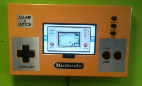
Here’s a wall hanging for the reception area that let’s your customers play retro games while they wait. To give you some sense of scale, the buttons to the right (labeled Start/Jump but we would call them A and B) are arcade buttons larger than traditional arcade buttons. The screen itself is a Samsung widescreen computer monitor — we’d wager that it’s a 16″ model but we’re just guessing. It’s held in the wooden frame by a piece of angle bracket.

This is the product of a hack we looked at in June where an Arduino was used to control digitized retro LCD games. The same hardware is used, monitoring the buttons with the Arduino and using a Python script to translate them to keypresses on a computer. That means this isn’t a standalone, but needs a computer to run the game and feed the LCD monitor. Still, we love the look of it and hold out hope that this will someday migrate to FPGA control (they have not problem driving LCD screens) with selectable games.

Lxardoscope Is A Linux+Arduino Oscilloscope

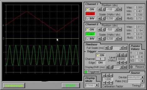
[Privatier] wrote in to let us know about lxardoscope, his project that lets you use an Arduino as hardware input for a Linux-based oscilloscope display. This implementation offers two channels with about 3000 samples per second from each. He touts some of the GUI options like vertical resolution between 2mV and 10V per division. That part kind of stumps us because we don’t see how a measurement of 10V (or more) can be taken using the schematic included. But you’re comprehension may surpass ours so do take a look yourself.

He is using an Arduino Uno for his testing. But to get around some issues he’s experienced with other USB-based solutions he implemented a serial port connection instead. You’ll need to remove the ATmega chip from the Arduino board after flashing the code to it, and then build a circuit around it which includes a power source where -2.5V is ground and 2.5V is VCC. All in all, you’ll need a 16 Mhz crystal, HEF4069 hex inverter, ATmega8-family microcontroller, and a few passive components to build this on a breadboard.

PIC LC Meter Improvements Add Li-Ion Battery And Charging Circuitry

[Trax] needed an LC meter and decided to use a tried-and-true design to build his own. The only problem was that he didn’t want to be tied to a bench supply or power outlet, which meant a bit of auxiliary design was in order. What he came up with is the battery-powered LC meter you see above.

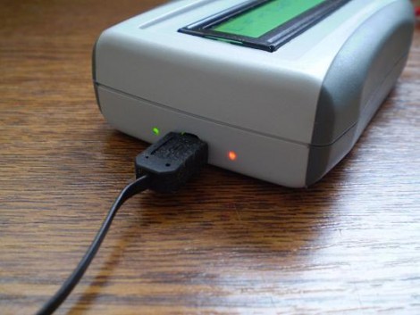
The core of the original [Phil Rice] design remains the same, with slight modifications to drive a different model of character LCD. The code is mostly unchanged, but some calibration routines became necessary after [Marko] noticed bugs in the behavior after power cycling. Now the device will perform what amounts to a hardware reset about 700ms after powering on or changing between inductance and capacitance measuring functions. The project box is quite small, and to get everything to fit [Marko] sourced the Lithium Ion battery from a Bluetooth headset. He needs 5V for the LCD screen so he used a TPS61222 boost converter. To top off the battery he’s included a MAX1811 single-cell Li-ion charger, which has a couple of status LEDs visible through the case as seen above.

[Thanks Marko]

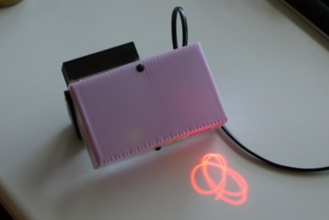
Laser Light Show Comes To Life From The Junk Bin

In a project that only spanned about three weeks [Lars] built this laser light show projector using parts scavenged from his junk bin. We’ve seen the concept many times before, all you need is a laser source and two mirrors mounted on a spinning bases. The laser diode for this project was pulled from a recordable DVD player. That beam passes through the optics from a laser printer to give it the focus necessary to get a good projected image.

[Lars] played around with the mirror angles until he achieved just the right look. The first mirror is mounted about 4 degrees from being flat with its motorized base; the second is off by about 6 degrees. This introduces slight oscillation in the beam direction when the motors are spinning. By adjusting the speed of each motor you get different patterns. Adjustments are happening completely at random thanks to the BasicStamp2 microcontroller which hadn’t been used in years. Fifteen lines of code were all it took.

Want a laser that’s not controlled at random? Check out this addressable galvanometer-based show.

Space Camera Streams Data During Flight

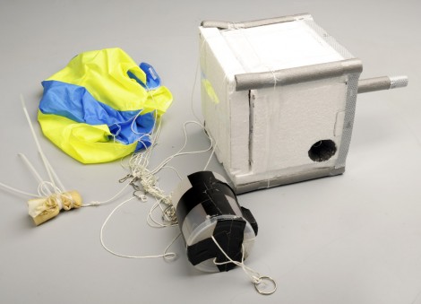
Take the risk of not recovering your hardware out of a near-space camera launch by streaming the data during flight. [Tim Zaman] is part of a team that developed the rig seen above. It sent 119 image back during the recent balloon launch. This included transmissions from as high as 36 kilometers.

The main hardware included a BeagleBoard with connected Webcam housed in a Styrofoam cooler for thermal protection. Pair that with a GPS module for location tracking, and a GPRS module for data transmission and you’re in business.

But that’s not all that went up. The team built a backup hardware module in case the primary failed. This one also had a GPS and GPRS radio, but was driven by an Arduino.

The radio connection made it easy to recover the hardware. GPS data led the team directly to the landing site. The package came to rest on the roof of a building, but we guess that’s more convenient than getting snagged at the top of a huge tree.

Don’t miss the hardware detail video that we’ve embedded after the break.

Continue reading “Space Camera Streams Data During Flight”