Using A Capacitor As An Actuator?!

[Dan Berard] has been using capacitors as actuators.

We’ve featured Dan’s awesome self built STM (scanning tunneling microscope) before. These microscopes work by moving a tip with nanometer precision across a surface. While the images he acquired are great, one disadvantage of the actuator he used is its poor rigidity. This limits the system to faster scan speeds.

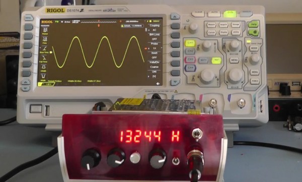
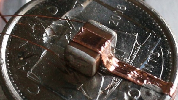
In his search for a better actuator [Dan] thought he’d try using MLCC capacitors! While not known for their electromechanical properties, you may have encountered capacitors that appear to “sing” (PDF), emitting an audible tone. This is due to the piezoelectric properties of BaTiO3. Effectively the capacitor acts as a weak piezo electric speaker.

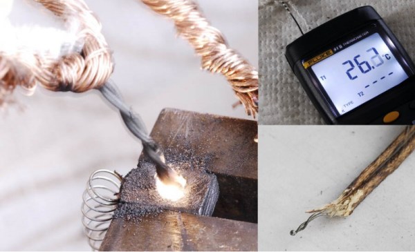
Using a 100V drive voltage [Dan] was able to get 300nm of deflection using the capacitor. To extend the range of the actuator he decided to ‘pole the ceramic dielectric’ this involved heating the capacitor above its Curie temperature of 120C. For this he used a transistor to heat the part as an ad-hoc hotplate. This increased the range of the actuator to 800nm, ideal for many STM (and other SPM) systems.

[Dan] is still weighing up his options for his next build, but MLCC capacitors are certainly a cheap and interesting choice.

Adventures With Vacuum Deposition Power Supplies

[macona] called this a “fail of the week”, but of course failure is just another part of the hacker adventure. Fail and fail often! He’s been slowly assembling a vacuum deposition system. These systems let you deposit thin films on a substrate. Vacuum deposition systems have all sorts of exciting applications, not only are they used in semiconductor manufacturing, but as [Ben Krasnow] has shown can create conductive transparent coatings. They’re even sometimes used for silvering mirrors.

A common feature of these systems is that they require high voltage, we’re not talking a few hundred volts or even a few thousand volts. But 10 to 20 kilovolts. You need such a high voltage in order to accelerate electrons and ions, which are used to eject atoms from a source and deposit them as a thin film on a substrate.

It was this HV supply [macona] was working on, cobbling the system together from parts found on eBay. Unfortunately he could only reach 9kv unloaded, which we’d expect to drop considerably under load. So [macona] has now found a different solution. But this teardown and write up still makes great reading.

We’re left to pondering on what projects the spare parts could be useful for: “I might be able to series the secondaries and get 30kv at 500ma! That would make one hell of a bug zapper! Actually these transformers scare the hell out of me….” me too Jerry! Me too!

Crack Open A USB Car Charger To Make It A Variable DC-DC Converter

[Boolean90] hacked a cheap USB car charger into a variable power supply. His proof of concept is to use this as a variable-speed motor controller. The best part is that nothing is being abused, the regulator inside is still running within manufacturer’s spec.

While we’ve seen similar hacks before, [Boolean90]s video is pretty cool and provides a nice insight into the components used in these cheap devices. Rather than a linear regulator, which would dissipate too much heat the device uses a common jelybean MC34063A (PDF) switching DC-DC converter which costs about 10 cents on eBay (about two dollars for twenty, shipped). Here it’s used to step the car batteries 12 volts down to 5, but can also be used in step-up and inverting configurations.

Like all switching buck converters the MC34063A uses a PWM (pulse width modulated) signal to drive an inductor and capacitor, which effectively form an LC filter. By controlling the pulse width, the output voltage can be regulated. [Afrotechmods] has a great tutorial on the basic principle. The regulation is controlled by feedback resistors. [Boolean90] simply added a variable resistor to allow the output voltage to be controlled.

Neat hack [Boolean90]! Continue reading “Crack Open A USB Car Charger To Make It A Variable DC-DC Converter”

Self Built Power Meter Uses Dual Sense Transformers

[Renaud] built a AC power meter from scratch. While commercial power meters like the Kill A Watt are available [Renaud’s] build gives an interesting insight into the methods used.

currentAt the heart of [Renaud’s] design lie two sense transformers. The first is a typical voltage stepdown transformer. This brings the AC line voltage down to +/- 10V, which is more amenable to digital sampling. The second is a current sense transformer. In current transformers the primary is typically a single wire (the AC line in this case) passing through the middle of a ring (see the picture to the right from wikipedia). The secondary is wrapped round the ring. When the secondary coil is shorted a current in the primary wire/coil induces a current in the secondary coil.

In practice, the voltage drop across a low value resistor is used to detect the current in the secondary. Clamp meters use this principle to make non-contact current measurements. Other power meters often use hall effect sensors for current measurements. It will be interesting to see how these methods compare when [Renaud] benchmarks this build.

[Renaud] takes the voltage and current readings from these transformers and samples them with a PIC in order to calculate power. As the AC voltage is periodic [Renaud] uses a method similar to Equivalent Time Sampling (ETS) to combine waveforms from multiple cycles and increase the effective sample rate.

Great stuff [Renaud]!

Hacker Reads Magnetic Stripe Card With Flatbed Scanner

[anfractuosus] has been reading magnetic stripe card… optically!

While hackers routinely read and write stripe cards, this is the first time we’ve reported on optically imaging and decoding data from the magnetic stripe. [anfratuosus] used a magnetic developer which is designed to allow visual inspection of the magnetic stripe. The developer uses micron sized iron particles in a suspension which are dropped onto the stripe. To the particles, the magnetic stripe looks like a series of magnets lined up. Long magnets striperepresent 0s and short magnets 1s. With each bit the orientation of the magnet changes, something like the diagram to the right. The magnetic field is strongest where the poles meet. So the iron particles are attracted to these flux reversal points on the stripe creating a visible pattern . There’s an awesome video of the process in action below.

While magnetic developer was designed for debugging faulty recording systems [anfratuosus] went a step further scanning the “developed” card, and writing a tool to decode the images and extract the card data. [anfratuosus] doesn’t mention any particular application, we love this circuitous hack anyway!

Continue reading “Hacker Reads Magnetic Stripe Card With Flatbed Scanner”

Build Your Own Function Generator

[Scullcom] has posted the second part of his function generator build tutorial. [Scullcom] previously posted the first part of this build which covered the XR2206 monolithic function generator IC on which his design is based. In this part [Scullcom] covers the output stages and final assembly.

We’ve covered digital and analog function generator builds before. [Scullcom]’s design complements these well by providing a detailed description of the design he used, and has provided full schematics and code from the Arduino Nano used in this project. The design covers audio frequencies (~40Hz to 30KHz) with square, sine and triangle wave outputs. While the XR2206 can’t compete with modern DDS function generators, if you’re a hacker on a budget and looking for a fun project this may be just the thing for you. And even if you don’t decide to build the one, you might find [Scullcom]’s description of the output stage interesting.

Great project [Scullcom] and we look forward to your next build!

Continue reading “Build Your Own Function Generator”

Hacker Creates Thermal Probes By Welding With A PC Power Supply

[Illya Tsemenko] decided to build his own thermocouples from bare wire. [Illya] is interested in measuring the temperature of Liquid Nitrogen and for this he needed T-type probes. While you can buy these for about 20 bucks, he felt this was too expensive for what is essentially two pieces of wire and decided to build his own.

Thermocouples use the Seebeck effect, when a piece of metal is hot at one end, and cold at the other the electrons in the hot end will be more energetic and migrate towards the cold end, creating a voltage. While this migration occurs in single metal, it can’t easily be measured (as the voltage will be the same as the measurement point). For that reason thermocouples use two metals in which the migration occurs at different rates. This difference creates an overall migration in one direction, and a voltage can be measured which correlates to the temperature where the metals meet. Thermocouples are extremely common and have many applications.

In order to make his thermocouples [Illya] needed to weld the two metals together, and knocked together a quick welding rig using a PC power supply and graphite electrode from a powertool. The graphite electrode is important as it prevents oxidization during the welding process.

The process worked well, and [Illya] was able to make both K and T-type thermocouples and successfully measure temperatures down to -190 degrees C. Awesome work [Illya]!