Custom Electronics And LED Panels Brighten Up A Nightclub

ledPanels

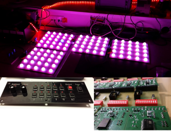
When [Robert] is presented with a challenge, he doesn’t back down. His friend dreamed of reusing some old LED panels by mounting them to the ceiling of the friend’s night club. Each panel consists of a grid of five by five red, green, and blue LEDs for a total of 75 LEDs per panel. It sounded like a relatively simple task but there were a few caveats. First, the controller box that came with the panels could only handle 16 panels and the friend wanted to control 24 of them. Second, the only input device for the controller was an infrared remote. The friend wanted an easy way for DJ’s to control the color of the panels and the infrared remote was not going to cut it. Oh yea, he also gave [Robert] just three weeks to make this happen.

[Robert] started out by building a circuit that could be duplicated to control each panel. The brain of this circuit is an ATtiny2313. For communication between panels, [Robert] chose to go with the DMX protocol. This was a good choice considering DMX is commonly used to control stage lighting effects. The SN75176 IC was chosen to handle this communication. In his haste to get this PCB manufactured [Robert] failed to realize that the LED panels were designed common cathode, as opposed to his 25 shiny new PCB’s which were designed to work with a common anode design. To remedy this, he switched out all of the n-channel MOSFET with p-channel MOSFET. He also spent a couple of hours manually cutting through traces and rewiring the board. After all of this, he discovered yet another problem. The LED’s were being powered from the same 5V source as the microcontroller. This lead to power supply issues resulting in the ATtiny constantly resetting. The solution was to add some capacitors.

Click past the break for more on [Robert’s] LED panels.

Continue reading “Custom Electronics And LED Panels Brighten Up A Nightclub”

Arduino garage door opener

Arduino Garage Door Opener Is Security Minded

Do it yourself garage door openers must be all the rage nowadays. We just got word of another take on this popular idea. [Giles] was commissioned by his friend to find a way to control the friend’s garage door using a smart phone. The request was understandable, considering the costly garage door remote and the fact that the buttons on the expensive remote tended to fail after a while. The inspiration for this project came from some YouTube videos of other similar projects. Those projects all paired an Arduino with a Bluetooth headset in order to control the door from a mobile phone. [Giles] understood that while this would get the job done, it wouldn’t be very secure. Bluetooth headsets typically connect to mobile phones using a four digit PIN. Many of them have known default PINs and even if the default is changed, it wouldn’t take very long to guess a four digit PIN. [Giles] knew he had to find a more secure way.

Continue reading “Arduino Garage Door Opener Is Security Minded”

This Sassy Art Installation Is Like The Stanley Parable For The Telephone

Insert Customer Feedback Here

Imagine this. A phone on a nearby desk starts ringing. No one is around to pick it up, so you decide that you will be a good Samaritan and answer the phone. You are greeted by a slightly creepy robotic female voice asking you to complete a simple survey. Having nothing else to do, you go ahead and run through the telephone survey. As you start answering the questions, things start to get a bit… weird. The robot voice doesn’t like your answers. She actually disagrees with you, and she does NOT like being interrupted. Now she’s getting sassy with you! What is going on here?

Most likely you are the latest victim of Insert Customer Feedback Here, [Charles’] art installation. You see, that is no ordinary telephone. [Charles] actually removed the guts of an old telephone and replaced them with an Arduino. The Arduino periodically rings the phone, waiting for someone to answer. Once the phone is off the hook, the Arduino uses a Wave shield to start playing back the scripted audio files. All of the text-to-speech files and the various hold music files are played back with the wave shield. The Arduino is also hooked up to the 1, 2, 3, and # keys of the telephone keypad in order to read back the user’s responses.

From here on out the program acts as a sort of “choose your own adventure” game. The program takes different paths and responds in different ways depending on how the user answers the questions. Generally speaking, it will get more “irritated” towards the user if it doesn’t “like” your answers, otherwise it will get less irritated. The hold music will even change to become more or less aggressive.

It’s easy to draw comparisons to Portal’s GLaDOS due to the robotic female voice and to the narrator from The Stanley Parable for the “choose your own adventure” feeling. In fact, if GLaDOS and The Stanley Parable had offspring, this would surely be it. This project brings that same type of silly sarcastic humor to a different medium and it does it well. Be sure to watch the video of the system in action below. It really starts to get interesting around the 1:15 mark. Continue reading “This Sassy Art Installation Is Like The Stanley Parable For The Telephone”

Never Miss A Thing With This Programmable Vacuum Fluorescent Display Ticker

VFD Ticker

[Coyt] wanted a more convenient way to keep up to date with the ever-changing Bitcoin exchange rates, as well as weather and other useful information. He realized that the vacuum fluorescent display (VFD) he had purchased a couple of years ago would be perfect to display small amounts of information.

[Coyt] discovered that the VFD had a serial interface. The problem was that the VFD was looking for a 12V serial signal but the Raspberry Pi he wanted to use runs at a 3.3V. Upon closer inspection [Coyt] discovered that the VFD actually ran at lower levels as well, but it had a level converter chip installed in front of the main connector. He simply bypassed the level converter and was then able to get the RasPi speaking directly to the VFD.

The brain running this display is a Raspberry Pi. The Pi runs a Python script that pulls down all of the relevant information from the internet and displays it on the VFD. [Coyt] didn’t stop there, though. He knew that having the screen on all of the time would be somewhat of a waste, so he hooked up a PIR sensor to automatically turn on the display only when needed. The PIR sensor can detect motion in the room and will disable the display after a set period of inactivity. Most of this is powered by an LM7805 voltage regulator. While [Coyt] admits a linear regulator is not his ideal solution, it does get the job done. The metal stand acts as a nice heat sink for the regulator.

[Coyt] also wanted his project to have a certain aesthetic. He started by bending a metal plate into a stand for the electronics. He then mounted the VFD on the front of the stand and the RasPi on the back. He also mounted green LEDs between the two plates to light up the edges for a little extra pizzazz. [Coyt] believes he can use the RasPi to PWM the LEDs but this has not yet been implemented. This would allow him to pulse the light for added effect.

Since the whole thing is run by a Python script, it would be trivial to modify it to display other kinds of information. What would you do if you had a motion sensitive automatic ticker?


Canadian Space Robot Will Repair Itself

The video above shows an animation of what the Canadian Space Agency hopes will be the first successful self-repair of the Mobile Servicing System aboard the ISS. The mobile servicing system is basically a group of several complicated robots that can either perform complicated tasks on their own, or be combined into a larger unit to extend the dexterity of the system as a whole.

The most recent addition to the servicing system is the Special Purpose Dexterous Manipulator, otherwise known as Dextre. Dextre is somewhat reminiscent of a human torso with two enormous arms. It is just one of the Canadian Space Agency’s contributions to the station. It was installed on the station in 2008 to perform activities that would normally require space walks. Dextre’s very first official assignment was successfully completed in 2011 when the robot was used to unpack two pieces for the Kounotori 2 transfer vehicle while the human crew on board the ISS was sleeping.

Dextre is constructed in such a way that it can be grabbed by the Canadarm2 robot and moved to various work sites around the Space Station. Dextre can then operate from the maintenance site on its own while the Canadarm2 can be used for other functions. Dextre can also be operated while mounted to the end of Canadarm2, essentially combining the two robots into one bigger and more dexterous robot.

One of the more critical camera’s on the Canadarm2 has started transmitting hazy images. To fix it, the Canadarm2 will grab onto Dextre, forming a sort of “super robot”. Dextre will then be positioned in such a way that it can remove the faulty camera. The hazy camera will then be mounted to the mobile base component of the Mobile Servicing System. This will give the ISS crew a new vantage point of a less critical location. The station’s human crew will then place a new camera module in Japan’s Kibo module’s transfer airlock. Dextre will be able to reach this new camera and then mount it on the Canadarm2 to replace the original faulty unit. If successful, this mission will prove that the Mobile Servicing System has the capability to repair itself under certain conditions, opening the door for further self-repair missions in the future.

Oculus Rift And Wii Balance Board Make Hoverboards A (Virtual) Reality

It’s almost 2015 and still don’t have the futuristic technology promised to us by Back to the Future Part II. Where are the flying cars, Mr. Fusions, or 19 Jaws movies? Most importantly, where are our hoverboards?

[cratesmith] got tired of waiting around and decided to take matters into his own hands. He combined the Oculus Rift virtual reality headset with the Wii Fit Balance Board to create a virtual hoverboard experience. He used the Unity3D engine (a favorite among Rift developers) to program the game engine. It’s a very rough demo right now, but the game comes complete with a simulated town to float around in and of course includes a model DeLorean.

Before you try to play this demo, you should know that it’s not without its faults. The primary problem [cratesmith] has experienced is with simulation sickness. His virtual reality system has no way to track body motion, which means that leaning back and forth on the Wii Fit board does not get translated to the equivalent virtual movement. The game must assume that the player stands straight up at all times, which is not an intuitive way to control something similar to a skateboard. The result is an off-putting experience that can break immersion and lead to a feeling of nausea.

A possible solution to this problem would be to use a camera style motion detector like the Microsoft Kinect. In fact, another Reddit user has recently posted a teaser video of another hoverboard simulator that uses the Oculus Rift, Wii Fit Board, and Kinect. Not much information is available about this second project, but we look forward to seeing updates in the future.

[createsmith] has not published the code for his demo because it’s still in the very early stages, but he has stated that he’s been giving it out to anyone who goes out of their way to ask. The hoverboard is probably the most coveted fictional technology from the 1989 adventure film. We know this because we’ve seen multiple projects over the years that were inspired by the movie.  We’re excited to see it come to fruition in any form.

[via Reddit]

1980’s Ingenuity Yields Mechanical Intervalometer

DIY Intervalometer

Let’s go back in time to the 1980’s, when shoulder pads were in vogue and the flux capacitor was first invented. New apartment housing was being built in [Vince’s] neighborhood, and he wanted some time-lapse footage of the construction. He had recently inherited an Elmo Super-8mm film camera that featured a remote control port and a speed selector. [Vince] figured he might be able to build his own intervalometer get some time-lapse footage of the construction. He was right.

An intervalometer is a device which counts intervals of time. These are commonly used in photography for taking time-lapse photos. You can configure the intervalometer to take a photo every few seconds, minutes, hours, etc. This photographic technique is great when you want see changes in a process that would normally be very subtle to the human eye. In this case, construction.

[Vince] started out by building his own remote control switch for the camera. A simple paddle-style momentary micro switch worked perfectly. After configuring the camera speed setting to “1”, he found that by pressing the remote button he could capture one single frame. Now all he needed was a way to press the button automatically every so often.

Being mechanically minded, [Vince] opted to build a mechanical solution rather than an electronic circuit. He first purchased a grandfather clock mechanism that had the biggest motor he could find. He then purchased a flange that allowed him to mount a custom-made wooden disk to the end of the minute hand’s axle. This resulted in a wheel that would spin exactly once per hour.

He then screwed 15 wood screws around the edge of the wheel, placed exactly 24 degrees apart. The custom paddle switch and motor assembly were mounted to each other in such a way that the wood screws would press the micro switch as they went by. The end result was a device that would automatically press the micro switch 15 times per hour. Continue reading “1980’s Ingenuity Yields Mechanical Intervalometer”