This week, Jonathan Bennett and Elliot Williams talk with Eben Upton about the Raspberry Pi! The conversation covers the new Pi 5, the upcoming CM5, the possible Pi500, and the Initial Public Offering (IPO) that may happen before too long. There’s also the PCIe port, the RP1, and the unexpected effects of using Broadcom chips. And then we ask the Billion Dollar question: What’s the money from an IPO going to fund? New hardware, software upgrades, better documentation? Nope, and the answer surprised us, too.
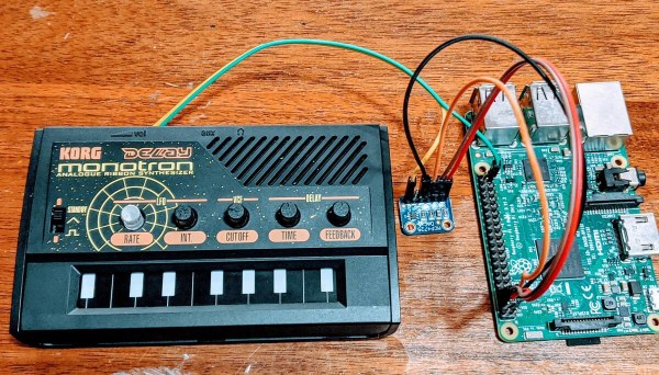
There are a handful of relatively dirt cheap synths out there like the KORG Monotron, but many of them use ribbon controllers that aren’t very precise. Ribbon controllers basically slide pots that you operate with your finger or a stylus. They’re painted to look like piano keys in order to show you approximately where the notes are supposed to be. The Stylophone is another extremely affordable synth that does even less as a synthesizer and uses this type of input. It’s a fun input if you don’t mind imprecision, but can be annoying otherwise.
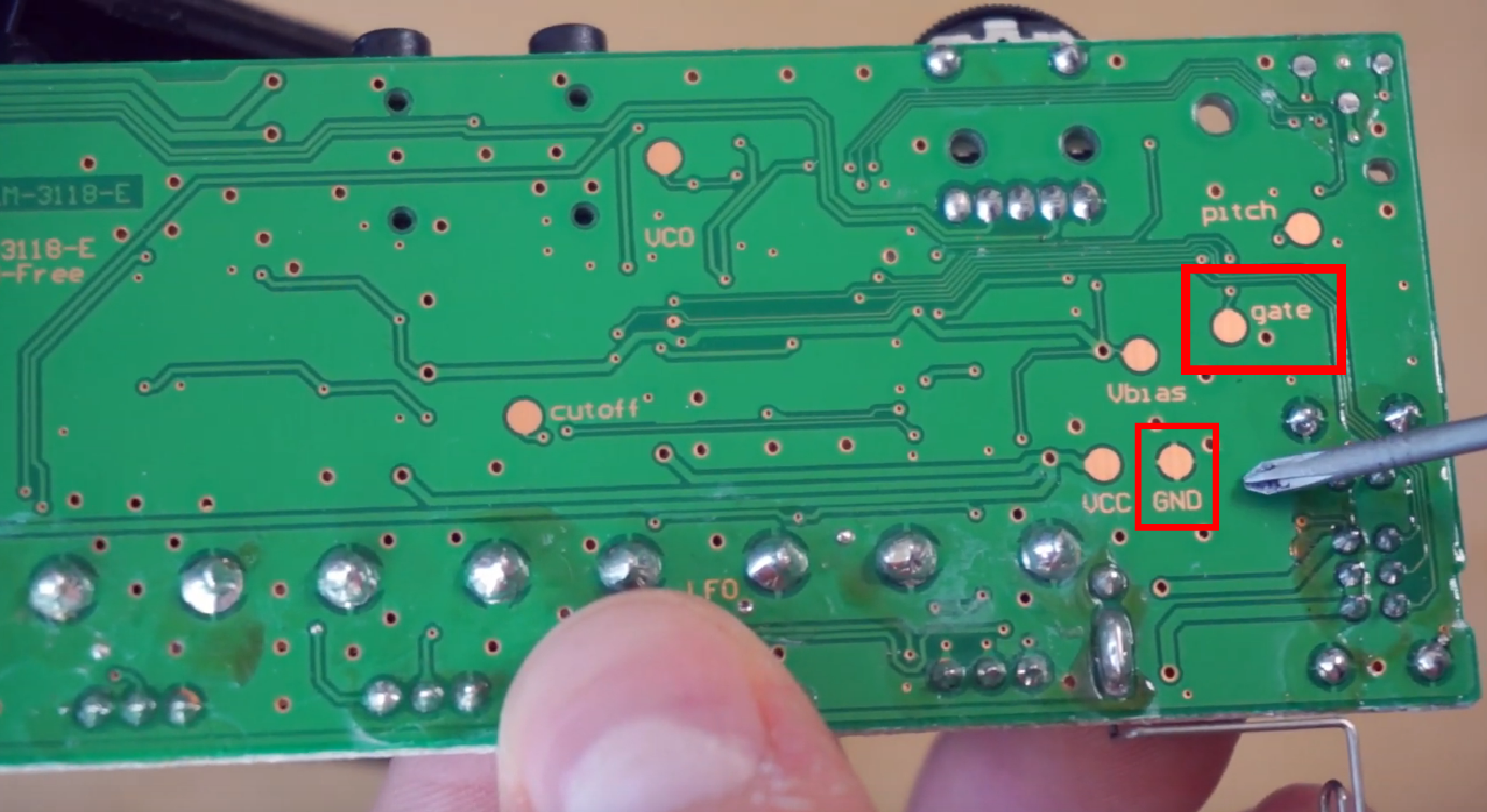
All it really took was a couple of solder joints in the right places, plus a clever Python script. The script listens for MIDI input from a keyboard, and then controls an MCP4725 DAC, which sends voltages to the Monotron. [schollz] wrote a tuning function that computes the FFT of the MIDI tones to find the fundamental frequencies of each to send along to the Monotron. Check it out after the break.
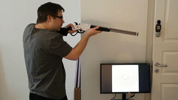
[Dirk] shared a fascinating project of his that consists of several different parts coming together in a satisfying whole. It’s all about wanting to do target practice, indoors, using a simple red laser dot instead of any sort of projectile. While it’s possible to practice by flashing a red laser pointer and watching where it lands on a paper target, it’s much more rewarding (and objective) to record the hits in some way. This is what led [Dirk] to create human-powered, battery-free laser guns with software to track and display hits. In the image above, red laser hits on the target are detected and displayed on the screen by the shooter.
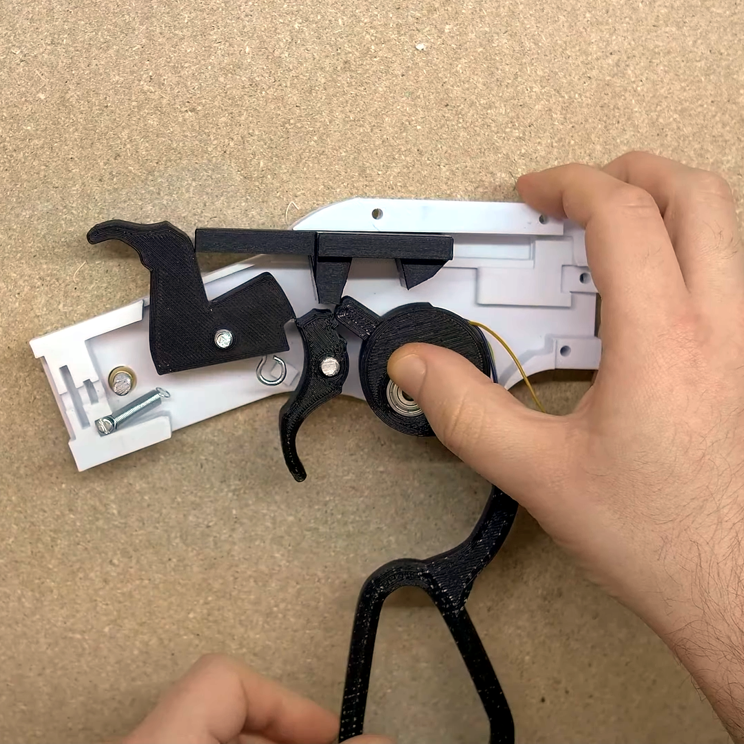
Right under the thumb is the pivot point for the lever, and that’s also where a geared stepper motor (used as a generator) is housed. Operating the action cranks the motor.
There are several parts to this project and, sadly, the details are a bit incomplete and somewhat scattered around, so we’ll go through the elements one at a time. The first is the guns themselves, and the star of the show is his 3D printed cowboy rifle design. The rifle paints the target with a momentary red laser dot when the trigger is pressed, but that’s not all. [Dirk] appears to have embedded a stepper motor into the lever action, so that working the lever cranks the motor as a generator and stores the small amount of power in a capacitor. Upon pulling the trigger, the capacitor is dumped into the laser (and into a piezo buzzer for a bit of an audio cue, apparently) with just enough juice to create a momentary flash. We wish [Dirk] had provided more details about this part of his build. There are a few more images here, but if you’d like to replicate [Dirk]’s work it looks like you’ll be on your own to some extent.
As for the target end of things, blipping a red dot onto a paper target and using one’s own eyeballs can do the job in a bare minimum sort of way, but [Dirk] went one further. He used Python and OpenCV with a camera to watch for the red dot, capture it, then push an image of the target (with a mark where the impact was detected) to a Chromecast-enabled screen near the shooter. This offers much better feedback and allows for easier scoring. The GitHub repository for the shot detector and target caster is here, and while it could be used on its own to detect any old laser pointer, it really sings when combined with the 3D printed cowboy rifle that doesn’t need batteries.
Not using projectiles in target practice does have some benefits: it’s silent, it’s easy to do safely, there is no need for a backstop, there are no consumables or cleaning, and there is no need to change or patch targets once they get too many holes. Watch it all in action in the video embedded below.
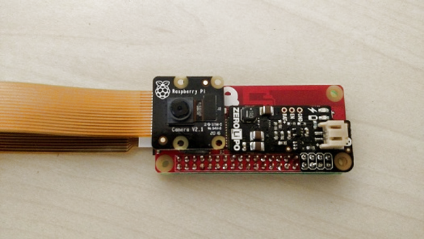
What makes [mwagner1]’s Raspberry Pi Zero-based WiFi camera project noteworthy isn’t so much the fact that he’s used the hardware to make a streaming camera, but that he’s taken care to document every step in the process from soldering to software installation. Having everything in one place makes it easier for curious hobbyists to get those Pi units out of a drawer and into a project. In fact, with the release of the Pi Zero W, [mwagner1]’s guide has become even simpler since the Pi Zero W now includes WiFi.
Using a Raspberry Pi as the basis for a WiFi camera isn’t new, but it is a project that combines many different areas of knowledge that can be easy for more experienced people to take for granted. That’s what makes it a good candidate for a step-by-step guide; a hobbyist looking to use their Pi Zero in a project may have incomplete knowledge of any number of the different elements involved in embedding a Pi such as basic soldering, how to provide appropriate battery power, or how to install and configure the required software. [mwagner1] plans to use the camera as part of a home security system, so stay tuned.
If Pi Zero camera projects catch your interest but you want something more involved, be sure to check out the PolaPi project for a fun, well-designed take on a Pi Zero based Polaroid-inspired camera.
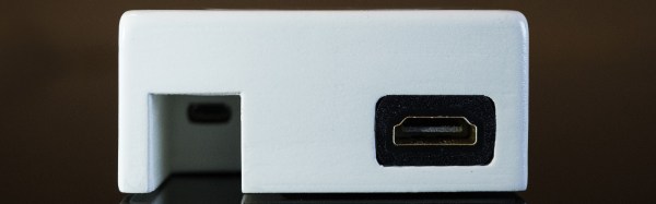
By far the most popular use for a Raspberry Pi is an emulation console. For an educational device, that’s fine – someone needs to teach kids how to plug a USB cable into a device and follow RetroPi tutorials on the Internet. These emulation consoles usually have one significant drawback: they’re ugly, with wires spilling everywhere. Instead of downloading a 3D printed Pi enclosure shaped like a Super Nintendo, [depthperfection] designed his own. It looks great, and doesn’t have a donglepocalypse hanging out the back.
The biggest factor in building an enclosure for a Pi Zero is how to add a few USB ports. There’s only one USB port on the Pi Zero, although if you’re exceptionally skilled, you can solder a hub onto the test points on the bottom of the board. This stackable USB hub solves the problem with the help of pogo pins for the power and USB pair. It’s only $17 USD, too.
With the USB and power sorted, [depthperfection] set out to design an enclosure. This was modeled in Fusion360, with proper vent holes, screw bosses, and cutouts for all the ports. It’s designed to be 3D printable, and with a little ABS smoothing, this enclosure looks great.
For software, [depthperfection] turned to Recallbox, a retrogaming platform that also doubles as a media player. It’s simpler than a RetroPi installation, but for playing Super Mario 3, you don’t really need many configuration options. This is a great project that just works and looks good doing it. The world — and the Raspberry Pi community — needs more projects like this, and we’re glad [depthperfection] sent this one in.
Wherever you stand on the topics of road safety and vehicle speed limits it’s probably fair to say that speed cameras are not a universally popular sight on our roads. If you want a heated argument in the pub, throw that one into the mix.
But what if you live in a suburban street used as a so-called “rat run” through route, with drivers regularly flouting the speed limit by a significant margin. Suddenly the issue becomes one of personal safety, and all those arguments from the pub mean very little.
Sample car speed measurements
[Gregtinkers]’ brother-in-law posted a message on Facebook outlining just that problem, and sadly the local police department lacked the resources to enforce the limit. This set [Gregtinkers] on a path to document the scale of the problem and lend justification to police action, which led him to use OpenCV and the Raspberry Pi camera to make his own speed camera.
The theory of operation is straightforward, the software tracks moving objects along the road in the camera’s field of view, times their traversal, and calculates the resulting speed. The area of the image containing the road is defined by a bounding box, to stop spurious readings from birds or neighbours straying into view.
[Coyt] wanted a more convenient way to keep up to date with the ever-changing Bitcoin exchange rates, as well as weather and other useful information. He realized that the vacuum fluorescent display (VFD) he had purchased a couple of years ago would be perfect to display small amounts of information.
[Coyt] discovered that the VFD had a serial interface. The problem was that the VFD was looking for a 12V serial signal but the Raspberry Pi he wanted to use runs at a 3.3V. Upon closer inspection [Coyt] discovered that the VFD actually ran at lower levels as well, but it had a level converter chip installed in front of the main connector. He simply bypassed the level converter and was then able to get the RasPi speaking directly to the VFD.
The brain running this display is a Raspberry Pi. The Pi runs a Python script that pulls down all of the relevant information from the internet and displays it on the VFD. [Coyt] didn’t stop there, though. He knew that having the screen on all of the time would be somewhat of a waste, so he hooked up a PIR sensor to automatically turn on the display only when needed. The PIR sensor can detect motion in the room and will disable the display after a set period of inactivity. Most of this is powered by an LM7805 voltage regulator. While [Coyt] admits a linear regulator is not his ideal solution, it does get the job done. The metal stand acts as a nice heat sink for the regulator.
[Coyt] also wanted his project to have a certain aesthetic. He started by bending a metal plate into a stand for the electronics. He then mounted the VFD on the front of the stand and the RasPi on the back. He also mounted green LEDs between the two plates to light up the edges for a little extra pizzazz. [Coyt] believes he can use the RasPi to PWM the LEDs but this has not yet been implemented. This would allow him to pulse the light for added effect.
Since the whole thing is run by a Python script, it would be trivial to modify it to display other kinds of information. What would you do if you had a motion sensitive automatic ticker?