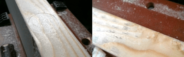
If you’ve done any woodworking in the past, odds are likely that you’ll eventually end up fixturing your stock in the crushing grip of a vise or C-Clamp. The results are painful, leaving a lasting impression of the clamp jaws on your beautiful, otherwise-unmarred piece of stock. Often, you’ll need to design around this issue, fixture it gently, or cushion the grip with a softer intermediate material. [Chimponabike] had other thoughts, though, and developed a technique for successfully popping the dimples out, returning clamped wood to its perfectly unmarred form.
The Technique itself is dead simple and takes only a few minutes to perform. Simply apply a small amount of water, let it seep into the wood, and then bring a hot iron down onto the soaked wood to evaporate off the soaked water–instantly inflating the wood back into its original form!
Last week, I covered some of the bitter details of an interesting hack that lets us split up the I²C clock line into multiple outputs with a demultiplexer, effectively giving us “Chip Selects” for devices with the same address.
This week, I figured it’d be best to layout a slightly more practical method for solving the same problem of talking to I²C devices that each have the same address.
I actually had a great collection of comments mention the same family of chips I’m using to tackle this issue, and I’m glad that we’re jumping off the same lead as we explore the design space.
Recalling the Work of Our Predecessors
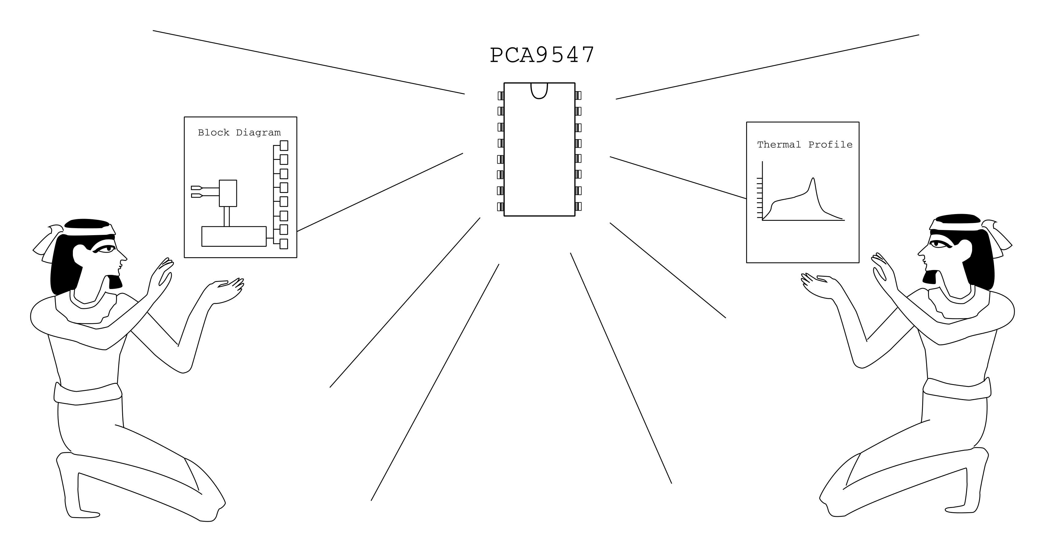
Before figuring out a clever way of hacking together our own solution, it’s best to see if someone before us has already gone through all of the trouble to solve that problem. In this case–we’re in luck–so much that the exact bus-splitting behavior we want is embedded into a discrete IC, known as the PCA9547.
It’s worth remembering that our predecessors have labored tirelessly to create such a commodity piece of silicon.
The PCA9547 (PDF) is an octal, I²C bus multiplexer, and I daresay, it’s probably the most practical solution for this scenario. Not only does the chip provide 8 separate buses, up to seven more additional PCA9547s can be connected to enable communication with up to 64 identical devices! What’s more, the PCA9547 comes with the additional benefit of being compatible with both 3.3V and 5V logic-level devices on separate buses. Finally, as opposed to last week’s “hack,” each bus is bidirectional, which means the PCA9547 is fully compliant with the I²C spec.
Selecting one of the eight I²C buses is done via a transfer on the I²C bus itself. It’s worth mentioning that this method does introduce a small amount of latency compared to the previous clock-splitter solution from last week. Nevertheless, if you’re planning to read multiple devices sequentially from a single bus anyway, then getting as close-as-possible to a simultaneous read/write from each device isn’t likely a constraint on your system.
With a breakout board to expose the pads, I mocked up a quick-n-dirty Arduino Library to get the conversation started and duplicated last week’s demo.
Happily enough, with a single function to change the bus address, the PCA9547 is pretty much a drop-in solution that “just works.” It’s definitely reassuring that we can stand on the shoulders of our chip designers to get the job done quickly. (They’ve also likely done quite a bit more testing to ensure their device performs as promised.) Just like last week, feel free to check out the demo source code up on Github.
With a sweeping wave of complexity that comes with using your new appliance tech, it’s easy to start grumbling over having to pull your phone out every time you want to turn the kitchen lights on. [Valentin] realized that our new interfaces aren’t making our lives much simpler, and both he and the folks at MIT Media Labs have developed a solution.
Open Hybrid takes the interface out of the phone app and superimposes it directly onto the items we want to operate in real life. The Open Hybrid Interface is viewed through the lense of a tablet or smart mobile device. With a real time video stream, an interactive set of knobs and buttons superimpose themselves on the objects they control. In one example, holding a tablet up to a light brings up a color palette for color control. In another, sliders superimposed on a Mindstorms tank-drive toy become the control panel for driving the vehicle around the floor. Object behaviors can even be tied together so that applying an action to one object, such as turning off one light, will apply to other objects, in this case, putting all other lights out.
Beneath the surface, Open Hybrid is developed on OpenFrameworks with a hardware interface handled by the Arduino Yún running custom firmware. Creating a new application, though, has been simplified to be achievable with web-friendly languages (HTML, Javascript, and CSS). The net result is that their toolchain cuts out a heavy need for extensive graphics knowledge to develop a new control panel.
If you can spare a few minutes, check out [Valentin’s] SolidCon talk on the drive to design new digital interfaces that echo those we’ve already been using for hundreds of years.
Last but not least, Open Hybrid may have been born in the Labs, but its evolution is up to the community as the entire project is both platform independent and open source.
Sure, it’s not mustaches, but it’s definitely more user-friendly.
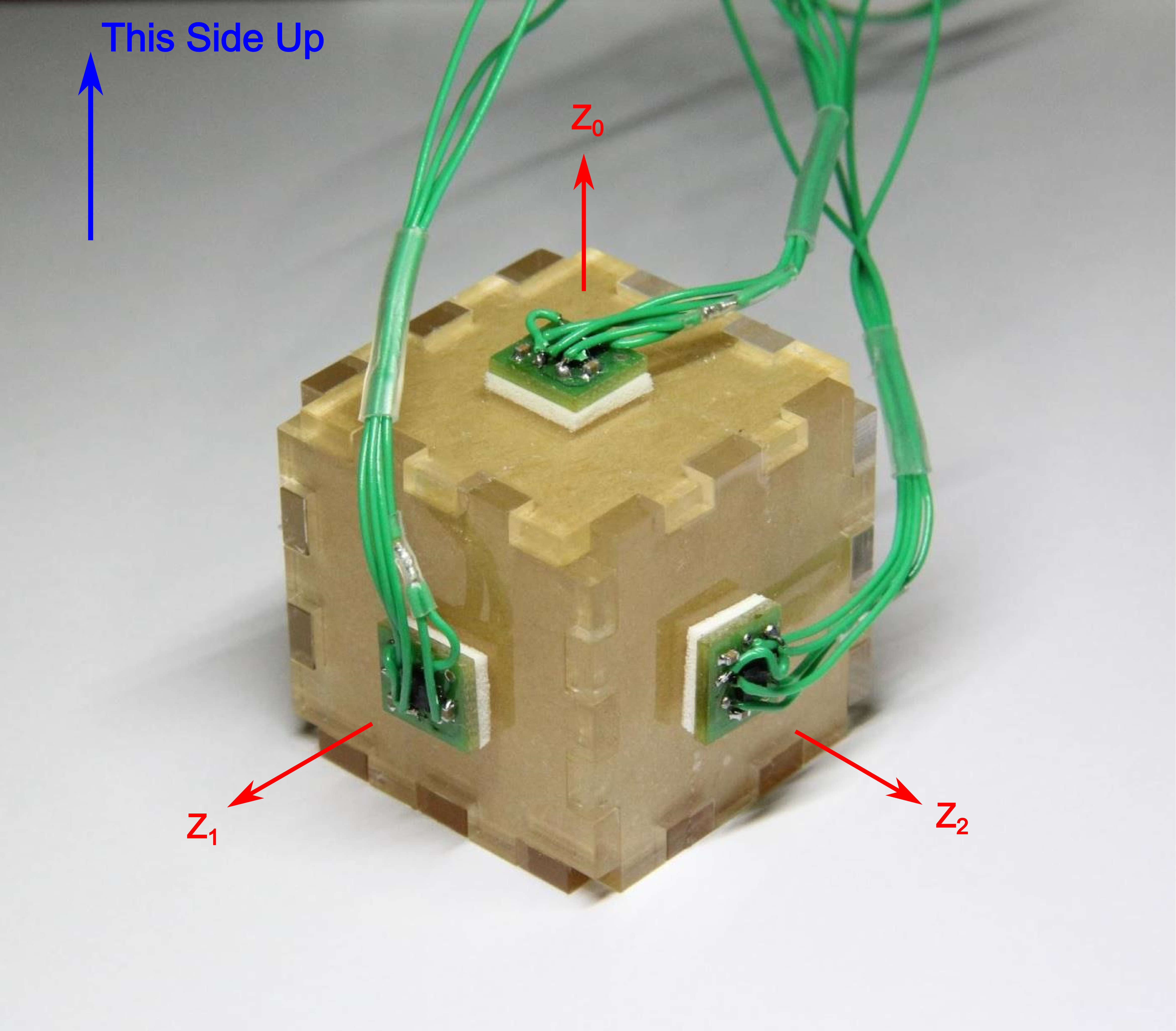
There comes a time when you need to wire up three, four, or more identical i2c devices to a common microcontroller. Maybe you’re thinking about driving 128 seven-segment displays with eight of those MAX6955 16-way digit drivers, or maybe you have a robot full of joints–each of which needs a BNO055 inertial sensor for angle estimation. (See above.) Crikey! In both of those cases, you’re best bet might be a schnazzy I²C device that can do most of the work for you. The problem? With a single I²C bus, there’s no standard way defined in the protocol for connecting two or more devices with the same address. Shoot! It would’ve been handy to wire up three BNO055 IMUs or eight MAX6955s and call it a day. Luckily, there’s a workaround.
We’ve seen some clever tricks in the past for solving this problem. [Marv G‘s] method involves toggling between a device’s default and alternate address with an external pin. This method, while clever, assumes that the device (a) has an alternate I²C address and (b) features an external pin for toggling that address.
I’ll introduce two additional methods for getting the conversation started between your micro’ and your suite of identical sensors. The first is “a neat trick,” but somewhat impractical for widespread use. The second is far more production-worthy–something you could gloat over and show off to your boss! Without further ado, let’s get started with Method 1.
Lastly, if you’d like to follow along, feel free to check out the source code on Github.
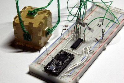
In both methods, I’m using the same sensor setup to check that each circuit behaves correctly. I happened to have a bunch of extra BMA180s on the bench, so I rolled out an example based on these chips. Back in the day, the BMA180 was a pretty common three-axis digital accelerometer. It has an I²C interface with two optional addresses. For the purpose of this example, I’m fixing them all with the same address. I’ve mounted three of these guys on mutually perpendicular axes of my acrylic “test cube,” and I’m reading each chip’s Z-axis. In this configuration I can easily pick out the gravity vector from the corresponding sensor as the data goes flying by my serial port window. If I can uniquely address each sensor and read the data, I’ve got a working circuit.
Method 1: Splicing Clocks into Chip-Selects
This method tips its hat towards SPI in that it behaves in an oddly similar fashion. If you’re feeling rusty on SPI, here’s a quick recap.
A Quick SPI Refreshment:
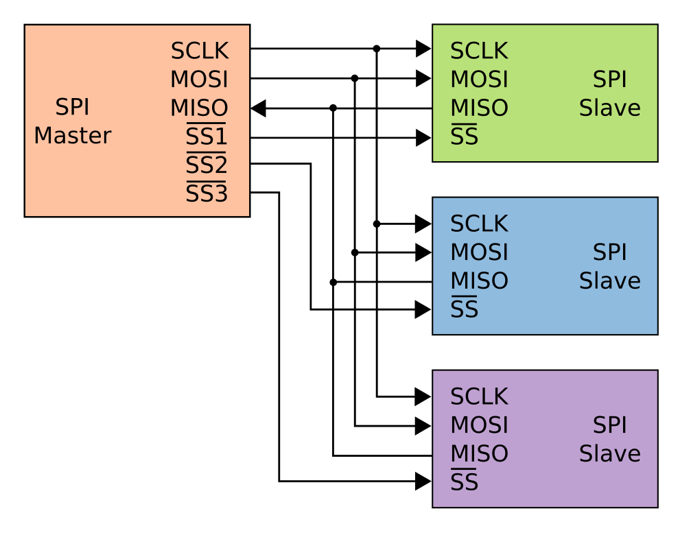
SPI, like I²C, is another protocol that shares both its clock and data lines with multiple slave devices. The difference, though, lies in the addressing scheme to talk to these devices that share the same bus. With SPI, while clock and data lines are shared, devices are addressed with separate chip-select (CS) lines.
The master microcontroller dedicates a unique output pin to each device (~SS1, ~SS2, and ~SS3 in this illustration). When the master micro’ wants to talk to a device, it asserts that device’s chip-select input pin by pulling it to logic LOW, and the conversation begins over the data bus. With the chip select LOW, the corresponding slave listens to the data on the bus. Meanwhile, all other devices ignore the conversation between the master and it’s chosen slave by keeping their bus pins in a high impedance state.
Giving I²C Its Own Chip-Selects:
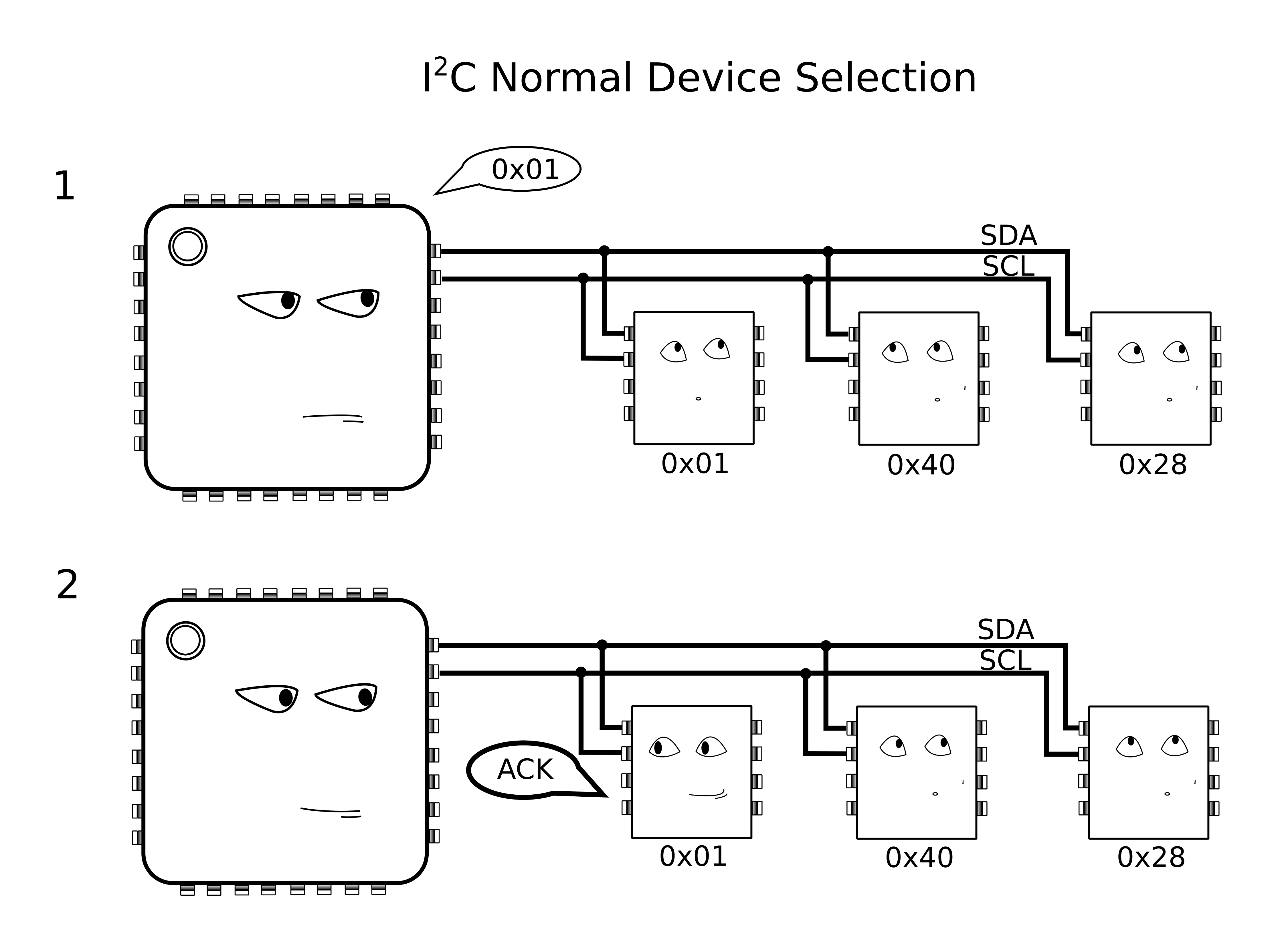
With I²C, Clock (SCL) and Data (SDA) lines are still shared between all I2C slave devices, but the addressing scheme happens by sending a message heard by all devices on the bus. To single out one device on the shared bus, the master first passes down the address of the slave device it wants to talk to, after which that slave replies with an ACKnowledge, and all other slaves ignore the data that follows until both data transmission is complete and the bus is “released.”
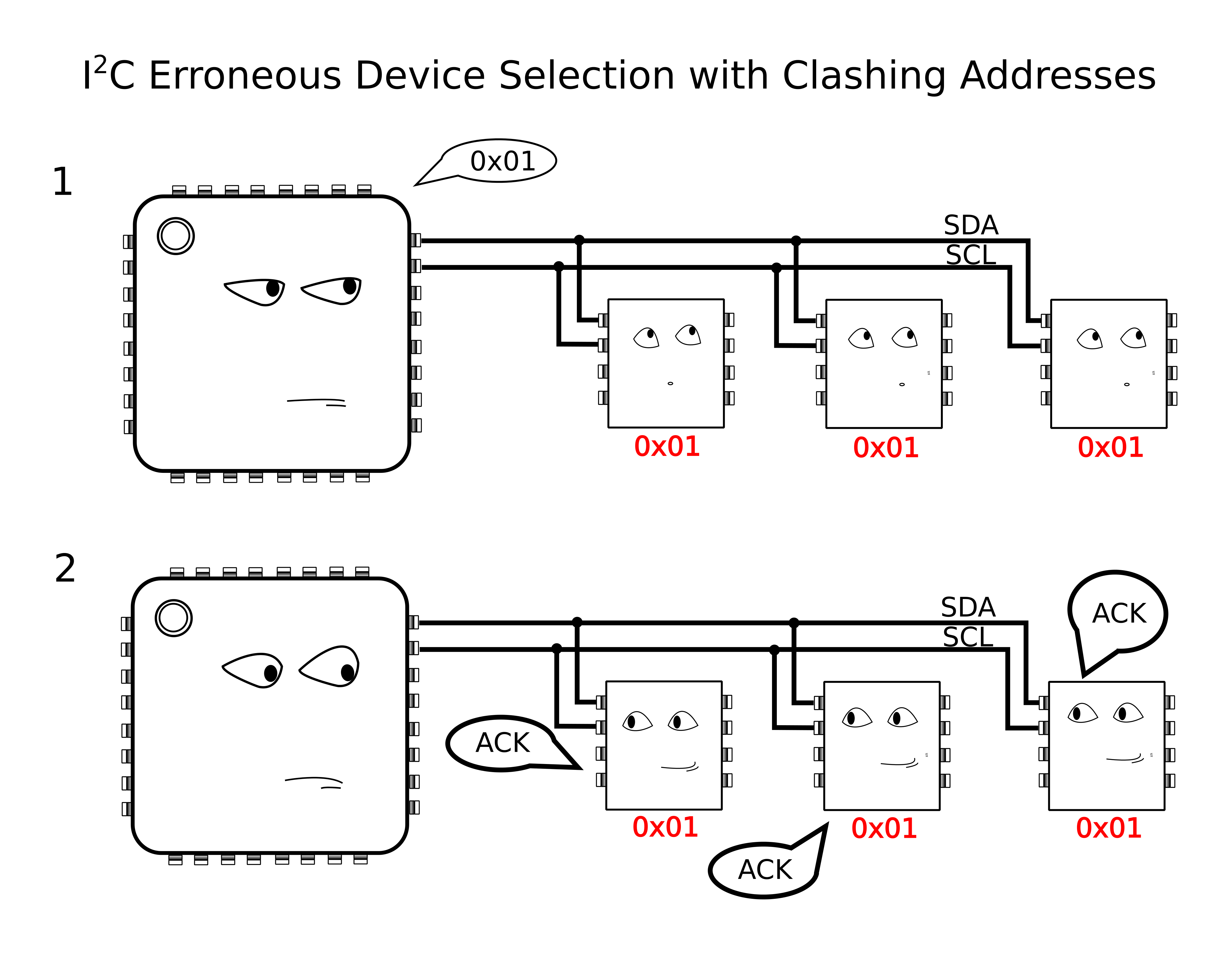
Because we have the problem of multiple devices with shared addresses, in theory, all of these devices would reply when the master passes down their shared address, and there’s no way for the master to single out a single device. In reality, this behavior is undefined on the I²C protocol.
Yikes! Anything goes when we wander away from defined behavior, so we try to avoid these things in practice.
The solution?
According to the I²C spec, It just so happens that an I²C slave device will ignore changes on the data line (SDA) provided that the clock line (SCL) is held high. In this method, I’ll “split” the SCL line into multiple SCL lines such that each shared I²C device gets its own SCL. By selectively rerouting the clock to each I²C device one-at-a-time, I’ve essentially turned the SCL line into a “chip select.”
To chop up that clock line, I’ll need a demultiplexer. A demultiplexer (or decoder) takes a logical input and reroutes it to one of several outputs based on the binary select lines.
I’ve dropped in the 74AC11138 eight-way demultiplexer for this task. It’s fast, capable of switching at megahertz rates, and its outputs default to logic HIGH. That second note is handy since idle SCL lines also default to logic HIGH.
The setup is shown in a simplified schematic above. In it, I’m using a Teensy 3.0 posing as the I²C bus master. To the right of the Teensy is the collection of identical chips, BMA180 accelerometers in this case. In the middle is the 74AC11138 eight-way demultiplexer.
Cons of this Method:
There’s a minor drawback with this technique, though, in that it doesn’t support I²C’s clock-stretching feature. Taking a step back, this method assumes that the SCL line is inherently unidirectional, controlled by only the I²C bus master. In other words, we’re making the assumption that data on the SCL line is only sent from master to slave and never the other way around. If your I²C slave devices implement clock-stretching, however, this assumption breaks down.
What is Clock Stretching?
Clock stretching is a method defined by the I²C protocol where the chip needs to “buy itself more time” and holds the SCL line low, hence, signalling to the master that it’s not ready for the upcoming data. In this scenario, the slave actively controls the SCL line, and it happens to be the only case where data moves up the SCL line from slave to master. In a setup with our demultiplexer between the master and our set of identical slaves, these slaves won’t be able to send back the clock-stretching signal to the master to indicate that they aren’t ready for data, if they happen to implement clock stretching. That said, clock stretching is a pretty rare feature among I²C-compatible devices, so this method is likely to work among a number of chips out now.
More Next Week
That’s all for Method 1. Thanks for tuning in, and check back next week for a slightly-more-professional method of tackling this same problem.
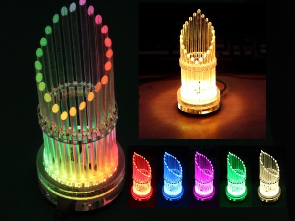
Light pipes are a pretty tricky feature to pull off. If the generic set on Digikey doesn’t meet your size and shape constraints, you’ll need to either find a vendor who can fabricate a specific shape for you or redesign that feature altogether. [Folker’s] LED Organ does an excellent job in piping light out from the source, and he does so in a way that’s reproducible with just a couple hours at the hand tools and a couple minutes on a laser cutter.
Hidden inside the base is a cluster of hardware that orchestrates the outer piece. 24 RGB LEDs are broken out into a ring and hidden in the base. [Folker’s] design enables control of the ring through either the LED player or LED Stamp with pattern-generation made possible by the free software, Jinx!
These days, exposed LEDs are ubiquitous enough among DIY electronics to almost be considered a hallmark of the DIY-enthusiast. Sure, “getting the project off the ground” is a great mindset to adopt when trying out some new firmware or components, but it can often leads us to a project’s finish with most of the wiring still exposed. While we’re certainly not offended by exposed LEDs, the task of concealing the shape of these components while also achieving the desired lighting effects is a challenge and rare sight to see. Our hats are off to the execution of this visual symphony.
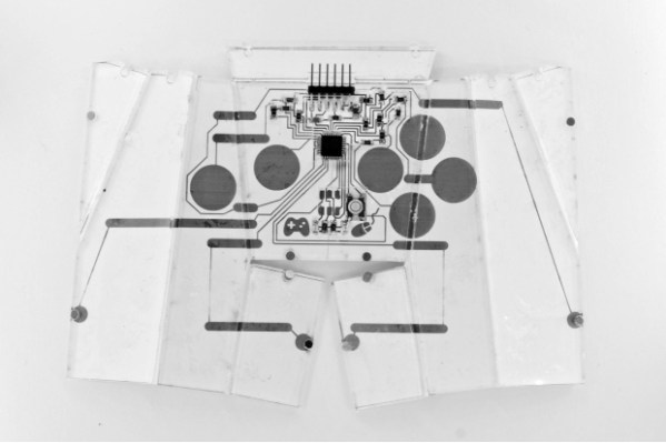
Still working with PCBs in 2D? Not [Yoav]. With some clever twists on the way we fab PCBs, he’s managed to create a state-aware foldable circuit board that responds to different configurations.
From his paper [PDF warning], [Yoav] discusses two techniques for developing foldable circuits that may be used repeatedly. The first method involves printing the circuit onto a flexible circuit board material and then bound front-and-back between two sheets of acrylic. Valid folded edges are distinguished by the edges of individual acrylic pieces. The second method involves laying out circuits manually via conductive copper tape and then exposing pads to determine an open or closed state.
Reconfigurable foldable objects may open the door for many creative avenues; in the video (after the break), [Yoav] demonstrates the project’s state-awareness with a simple onscreen rendering that echoes its physical counterpart.
While these circuits are fabbed from a custom solution, not FR1 or FR4, don’t let that note hold your imagination back. In fact, If you’re interested with using PCB FR4 as a structural element, check out [Voja’s] comprehensive guide on the subject.
For many of us, interacting with computers may be as glorious as punching keys and smearing touch screens with sweaty fingers and really bad posture. While functional, it’s worth reimagining a world where our conversation with technology is far more intuitive, ergonomic, and engaging. Enter TEI, an annual conference devoted to human-computer interaction and a landmark for novel projects that reinvent the conventional ways we engage our computers. TEI isn’t just another sit-down conference to soak in a wealth of paper talks. It’s an interactive weekend that combines these talks with a host of workshops provided by the speakers themselves.
Last year’s TEI brought us projects like SPATA, digital calipers that sped up our CAD modeling by eliminating the need for a third hand, and TorqueScreen, a force-feedback mechanism for tablets and other handhelds.
Next February’s conference is no exception for new ways to interact with novel technology. To get a sense of what’s to come, here’s a quick peek into the past from last year’s projects:
 The Technique itself is dead simple and takes only a few minutes to perform. Simply apply a small amount of water, let it seep into the wood, and then bring a hot iron down onto the soaked wood to evaporate off the soaked water–instantly inflating the wood back into its original form!
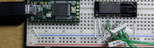


 I’ve dropped in the 74AC11138 eight-way demultiplexer for this task. It’s fast, capable of switching at megahertz rates, and its outputs default to logic HIGH. That second note is handy since idle SCL lines also default to logic HIGH.