If you’re a regular reader of Hackaday, you may have noticed a certain fondness for Meshtastic devices, and the LoRa protocol more generally. LoRa is a great, low-power radio communications standards, but sometimes the antennas you get with the modules can leave you wanting more. That’s why [Chris Prioli] at the Gloucester County Amateur Radio Club in the great state of New Jersey have got a Yagi antenna for North America’s 915 MHz LoRa band.
Right out the gate, their article links to one of ours, where [tastes_the_code] builds a Yagi antenna for the European 868 MHz LoRa. Like [tastes_the_code], the radio club found [Chris]’s antenna gives much better reception than what came with the LoRa module. Looking out their window, instead of two Metastatic nodes with a stock antenna, one club member is now connecting to two hundred.
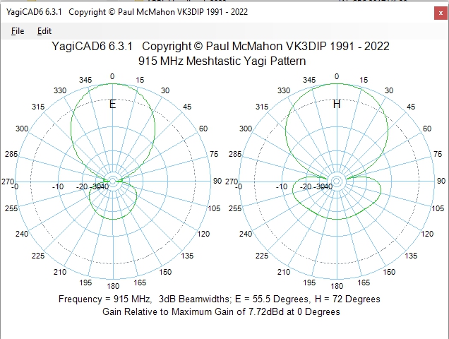
Now, the Yagi is directional, so you only get that boost pointed down the axis of the antenna, but at least in simulation they estimate a 7.7 dB front-to-back gain vs under 3 dB for an omnidirectional antenna. Not bad, for a simple 3D print and some stiff wire!
If you don’t want to re-invent the wheel again, check out the GCARC’s GitHub for files if you’re in North America. If you’re in Europe, check out [taste_the_code]’s build from last year. Of course whatever band you’re operating in, Yagi isn’t your only roll-your-own option for a LoRa antenna.
Thanks to [Jon Pearce WB2MNF] for the tip!