If you are a fan of set theory, you might agree there are two sets of people who write computer programs: those who know what a Bloom filter is and those who don’t. How could you efficiently test to see if someone is one set or another? Well, you could use a Bloom filter. [SamWho] takes us through the whole thing in general terms that you could apply in any situation.
The Bloom filter does perform a trade-off for its speed. It is subject to false positives but not false negatives. That is, if a Bloom filter algorithm tells you that X is not part of a set, it is correct. But if it tells you it is, you may have to investigate more to see if that’s true.
If it can’t tell you that something is definitely in a set, why bother? Usually, when you use a Bloom filter, you want to reduce searching through a huge amount of data. The example in the post talks about having a 20-megabyte database of “bad” URLs. You want to warn users if they enter one, but downloading that database is prohibitive. But a Bloom filter could be as small as 1.8 megabytes. However, there would be a 1 in 1000 chance of a false positive.
 Increase the database size to 3.59 megabytes, and you can reduce false positives to one in a million. Presumably, if you got a positive, you could accept the risk it is false, or you could do more work to search further.
Imagine, for example, a web cache device or program. Many web pages are loaded one time and never again. If you cache all of them, you’ll waste a lot of time and push other things out of the cache. But if you test a page URL with a Bloom filter, you can improve things quite a bit. If the URL may exist in the Bloom filter, then you’ve probably seen it before, so you might want to cache it.
If it says you haven’t, you can add it to the filter so if it is ever accessed again, it will cache. Sure, sometimes a page will show a false positive. So what? You’ll just cache the page on the first time, which is what you did before, anyway. If that happens only 0.1% of the time, you still win.
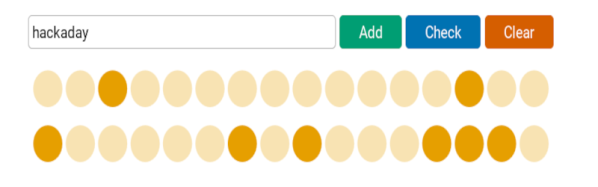
In simple terms, the Bloom filter hashes each item using three different algorithms and sets bits in an array based on the result. To test an item, you compute the same hashes and see if any of the corresponding bits are set to zero. If so, the item can’t be in the set. Of course, there’s no assurance that all three bits being set means the set contains the item. Those three bits might be set for totally different items.
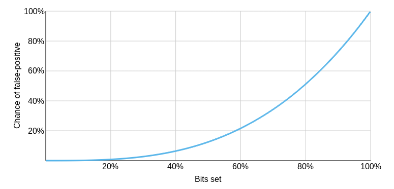
Why does increasing the number of bits help? The post answers that and looks at other optimizations like a different number of hash functions and counting.
The post does a great job of explaining the filter but if you want a more concrete example in C, you might want to read this post next. Or search for code in your favorite language. We’ve talked about Python string handling with Bloom filters before. We’ve even seen a proposal to add them to the transit bus.