Whether you only dabble in electronics as a hobby or it’s your full-time job, there are few tools as indispensable as the multimeter. In fact, we’d be willing to bet nearly everyone reading this site owns at least one of them. But as common and mindbogglingly useful as they may be, they aren’t perfect. Even the high-end models will invariably have some annoyance that only reveals itself once you become intimately acquainted with it.
Most people would just live with those quirks, especially when dealing with a cheaper model. But not [John Duffy]. Deciding nothing but perfection would do, he took every favorite feature he’d ever run into while using other multimeters and combined them into his scratch-built HydraMeter. In the process, he managed to come up with a few new ideas that push this device into a league of its own.
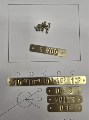
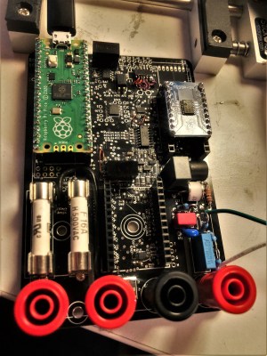 Some of the features of the HydraMeter will look familiar. You might even have them on your own personal meter, such as the wireless removable display module. Other features you’ll wish your meter had, such as the removable cartridge on the front of the device that lets you rapidly swap out a burned fuse. On the other side of the spectrum, there are some esoteric features that might leave you scratching your head. The ability to tell exactly how the meter is configured at a glance thanks to its exclusive use of toggle switches has a certain hacker appeal, but it’s a tricky user interface for most folks.
While the overall design of the HydraMeter may be divisive, one thing we can all agree on is that getting the project to this state took incredible determination. Over the years we’ve only seen a handful of individuals attempt to develop their own multimeters, and even then, none of them approached this level of fit and finish. The fact that [John] has turned all that effort over to the community by releasing his design under the CERN license is truly admirable.
[John] brought the HydraMeter out to Pasadena back in November for Supercon, and it got quite a reaction. And if you don’t like the user interface, it’s not hard to imagine how you could change it. This project has unquestionably pushed the state of the art for open source multimeters forward, and we’re eager to see where it goes from here.
Continue reading “Open Source Multimeter Raises The Bar For DIY Tools” →