Frustrated by his Aldi multimeter’s backlight turning off after just 15 seconds, [Steg Steg] took matters into his own hands. His solution? He added a manual toggle switch to control the backlight, allowing it to stay on as long as needed. He began by disassembling the multimeter—removing the outer bumper and a few screws—to access the backlight, labeled “BL.” He identified the voltage regulator outputting 2.8 V, desoldered the red wire, and extended it to install the switch.
On his first try, he successfully drilled a spot for the SPST switch. To fit the switch into the multimeter’s rubber bumper, he used a circular punch, although his second hole wasn’t as clean as the first. Despite this minor setback, the modification worked perfectly, giving him complete control over his multimeter’s backlight without the original 15-second timeout.
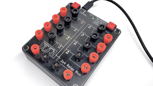
Multimeters are a bit like potato chips: you can’t have just one. But they’re a lot more expensive than potato chips, especially the good ones, and while it’s tempting to just go get another one when you need to make multiple measurements, sometimes it’s not practical. That’s why something like this 2×4 relay-based multiplexer might be a handy addition to your bench
In this age of electronics plenty, you’d think that a simple USB relay board would be easy enough to lay hands on. But [Petteri Aimonen] had enough trouble finding a decent one that it became easier to just roll one up from scratch. His goal was to switch both the positive and negative test leads from up to four instruments to a common set of outputs, and to have two independent switching banks, for those times when four-lead measurements are needed. The choice of relay was important; [Petteri] settled on a Panasonic DPDT signal relay with low wetting current contacts and a low-current coil. The coils are driven by a TBD62783A 8-channel driver chip, while an STM32 takes care of USB duties.
The mechanical design of this multiplexer is just as slick as the electrical. [Petteri] designed the PCB to act as the cover for a standard Hammond project box, so all the traces and SMD components are mounted on the back. That just leaves the forest of banana-plug binding posts on the front, along with a couple of pushbuttons for manual input switching and nicely silkscreened labels. The multiplexer is controlled over USB using the SCPI protocol, which happily includes an instrument class for signal switchers.
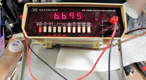
Inspired by electronics repair videos on YouTube, [Steven Leibson] recently found himself hunting down something to fix on eBay. This ‘something’ ended up being a certified classic: a Keithley Model 179 digital multimeter from 1978. Listed as non-functional, the unit arrived at his door for less than $50. There weren’t any exciting pops or smoke when he powered it on, but the display seemed to be showing nothing but random nonsense.
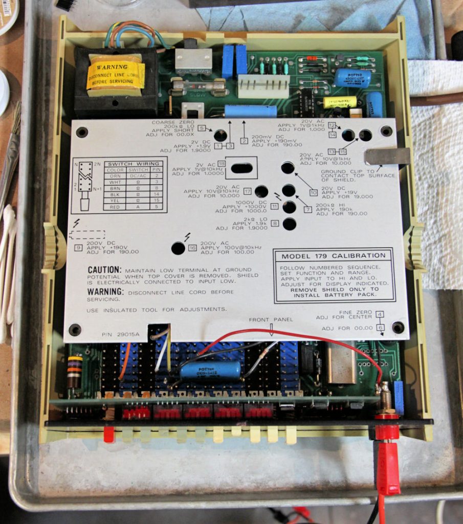
The meter has a convenient calibration sequence printed on its electrostatic shield cover and a deadly exposed AC line fuse in the upper left part of the photo.
Ultimately reviving this little piece of history was quite simple, with the main issue turning out to be a dodgy inter-board connector between the main and display boards. After admiring an old repair attempt made on the component, he removed both the male and female connectors, replacing them with new ones.
This uncovered issues with the PCB, as the FR4 material and the traces on it had begun to delaminate, probably due to the old adhesive giving up due to age. With pretty low trace density this wasn’t anything that a bit of care couldn’t work around, fortunately.
Before finding this dodgy connector, [Steven] first tried to clean the front mechanical connectors, which took multiple sessions. This was followed up by oiling the mechanism. With the connector fixed and some cleaning, the meter’s display now read correctly. It still has some issues with starting up though, which [Steven] reckons are due to the old capacitors in the device.
Presumably some recapping will round off this fun device revival experience, but for the time being a Keithley Model 179 has been saved from e-waste, to inspire generations to come.
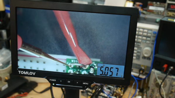
Some things go together, like chocolate and peanut butter. Others are more odd pairings, like bananas and bacon. We aren’t sure which category to put [IMSAI Guy]’s latest find in. He has a microscope with a built-in digital multimeter. You can see the video of the device in operation below.
The microscope itself is one of those unremarkable ten-inch LCD screens with some lights and a USB camera. But it also has jacks for test probes, and the display shows up in the corner of the screen. It is a normal enough digital meter except for the fact that its display is on the screen.
If you had to document test results, this might be just the ticket. If you are probing tiny little SMD parts under the scope, you may find it useful, too, so you don’t have to look away from what you are working on when you want to take a measurement. Although for that, you could probably just have a normal display in the bezel, and it would be just as useful.
At about $180 USD, it’s not exactly an impulse buy. We wonder if we’ll someday see an oscilloscope microscope. That might be something. These cheap microscopes are often just webcams with additional optics. You can do the same thing with your phone. If you don’t need the microscope, but you like the idea, can we interest you in a heads-up meter?
Multimeters are indispensable tools when working on electronics. It’s almost impossible to build any but the most basic of circuits without one to test and troubleshoot potential issues, and they make possible a large array of measurement capabilities that are not easily performed otherwise. But when things start getting a little more complex it’s important to know their limitations, specifically around what they will tell you about circuits designed for high frequency. [watersstanton] explains in this video while troubleshooting an antenna circuit for ham radio.
The issue that often confuses people new to radio or other high-frequency projects revolves around the continuity testing function found on most multimeters. While useful for testing wiring and making sure connections are solid, they typically only test using DC. When applying AC to the same circuits, inductors start to offer higher impedance and capacitors lower impedance, up to the point that they become open and short circuits respectively. The same happens to transformers, but can also most antennas which often look like short circuits to ground at DC but can offer just enough impedance at their designed frequency to efficiently resonate and send out radio waves.
This can give some confusing readings, such as when testing to make sure that a RF connector isn’t shorted out after soldering it to a coaxial cable for example. If an antenna is connected to the other side, it’s possible a meter will show a short at DC which might indicate a flaw in the soldering of the connector if the user isn’t mindful of this high-frequency impedance. We actually featured a unique antenna design recently that’s built entirely on a PCB that would show this DC short but behaves surprisingly well when sending out WiFi signals.
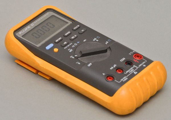
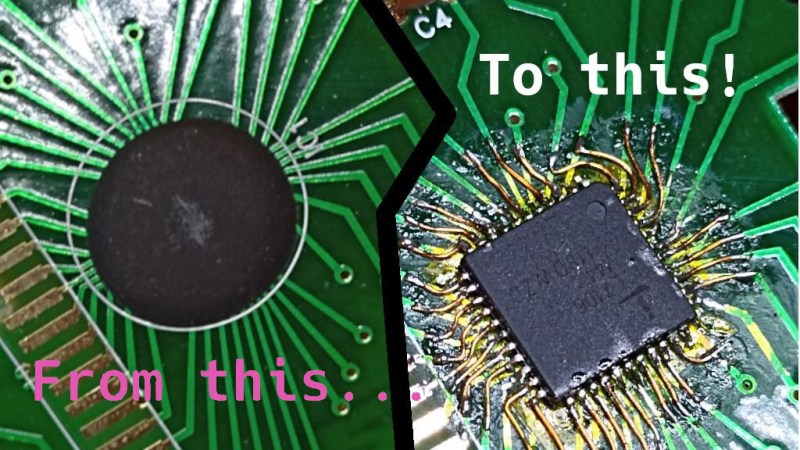
The black blobs on cheap PCBs haunt those of us with a habit of taking things apart when they fail. There’s no part number to look up, no pinout to probe, and if magic smoke is released from the epoxy-buried silicon, the entire PCB is toast. That’s why it matters that [Throbscottle] shared his journey of repairing a vintage multimeter whose epoxy-covered single-chip-multimeter ICL7106 heart developed an internal reference fault. When a multimeter’s internal voltage reference goes, the meter naturally becomes useless. Cheaper multimeters, we bin, but this one arguably was worth reviving.
[Throbscottle] doesn’t just show what he accomplished, he also demonstrates exactly how he went through the process, in a way that we can learn to repeat it if ever needed. Instructions on removing the epoxy coating, isolating IC pins from shorting to newly uncovered tracks, matching pinouts between the COB (Chip On Board, the epoxy-covered silicon) and the QFP packages, carefully attaching wires to the board from the QFP’s legs, then checking the connections – he went out of his way to make the trick of this repair accessible to us. The Instructables UI doesn’t make it obvious, but there’s a large number of high-quality pictures for each step, too.
The multimeter measures once again and is back in [Throbscottle]’s arsenal. He’s got a prolific history of sharing his methods with hackers – as far back as 2011, we’ve covered his guide on reverse-engineering PCBs, a skillset that no doubt made this repair possible. This hack, in turn proves to us that, even when facing the void of an epoxy blob, we have a shot at repairing the thing. If you wonder why these black blobs plague all the cheap devices, here’s an intro.
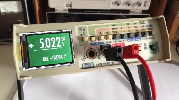
Old lab equipment was often built to last, and can give decades of service when treated properly. It’s often so loved that when one part fails, it’s considered well worth repairing rather than replacing with something newer. [Michael] did just that, putting in the work to give his Fluke 8050A multimeter a shiny new display.
The Fluke 8050A is a versatile device, capable of measuring voltage, current, and resistance in addition to decibels at various impedences and conductance, too. The original display doesn’t show some of the finer details so well, so [Michael] elected to improve on that when he installed a new 2.2″ graphical LCD to replace the basic 7-segment LCD that originally came with the hardware.
To achieve the install, the original LCD display module was removed from the chassis. A piggyback device that sits under the Fluke’s microcontroller was then used to break out signals for the new graphical LCD without requiring modification to the meter’s PCB itself. An Atmega32u4 microcontroller then takes in these signals, and then drives the graphical LCD accordingly.
It’s a great hack that makes the old multimeter easier to use, and the new white-on-green display is far kinder on the eyes, too. We’ve seen other multimeters get screen transplants before, too. Of course, if you’re new to the world of segmented LCDs and want to learn more about how they work, [Joey Castillo]’s talk from last year’s Remoticon will get you up to speed!