Coax Stub Filters Demystified

Unless you hold a First Degree RF Wizard rating, chances are good that coax stubs seem a bit baffling to you. They look for all the world like short circuits or open circuits, and yet work their magic and act to match feedline impedances or even as bandpass filters. Pretty interesting behavior from a little piece of coaxial cable.

If you’ve ever wondered how stub filters do their thing, [Fesz] has you covered. His latest video concentrates on practical filters made from quarter-wavelength and half-wavelength stubs. Starting with LTspice simulations, he walks through the different behaviors of open-circuit and short-circuit stubs, as well as what happens when multiple stubs are added to the same feedline. He also covers a nifty online calculator that makes it easy to come up with stub lengths based on things like the velocity factor and characteristic impedance of the coax.

It’s never just about simulations with [Fesz], though, so he presents a real-world stub filter for FM broadcast signals on the 2-meter amateur radio band. The final design required multiple stubs to get 30 dB of attenuation from 88 MHz to 108 MHz, and the filter seemed fairly sensitive to the physical position of the stubs relative to each other. Also, the filter needed a little LC matching circuit to move the passband frequency to the center of the 2-meter band. All the details are in the video below.

It’s pretty cool to see what can be accomplished with just a couple of offcuts of coax. Plus, getting some of the theory behind those funny little features on PCBs that handle microwave frequencies is a nice bonus. This microwave frequency doubler is a nice example of what stubs can do.

Continue reading “Coax Stub Filters Demystified”

Hackaday Links Column Banner

Hackaday Links: July 21, 2024

When monitors around the world display a “Blue Screen of Death” and you know it’s probably your fault, it’s got to be a terrible, horrible, no good, very bad day at work. That’s likely the situation inside CrowdStrike this weekend, as engineers at the cybersecurity provider struggle to recover from an update rollout that went very, very badly indeed. The rollout, which affected enterprise-level Windows 10 and 11 hosts running their flagship Falcon Sensor product, resulted in machines going into a boot loop or just dropping into restore mode, leaving hapless millions to stare at the dreaded BSOD screen on everything from POS terminals to transit ticketing systems.

Continue reading “Hackaday Links: July 21, 2024”

Welding Wood Is As Simple As Rubbing Two Sticks Together

Can you weld wood? It seems like a silly question — if you throw a couple of pieces of oak on the welding table and whip out the TIG torch, you know nothing is going to happen. But as [Action Lab] shows us in the video below, welding wood is technically possible, if not very practical.

Since experiments like this sometimes try to stretch things a bit, it probably pays to define welding as a process that melts two materials at their interface and fuses them together as the molten material solidifies. That would seem to pose a problem for wood, which just burns when heated. But as [Action Lab] points out, it’s the volatile gases released from wood as it is heated that actually burn, and the natural polymers that are decomposed by the heat to release these gases have a glass transition temperature just like any other polymer. You just have to heat wood enough to reach that temperature without actually bursting the wood into flames.

His answer is one of the oldest technologies we have: rubbing two sticks together. By chucking a hardwood peg into a hand drill and spinning it into a slightly undersized hole in a stick of oak, he created enough heat and pressure to partially melt the polymers at the interface. When allowed to cool, the polymers fuse together, and voila! Welded wood. Cutting his welded wood along the joint reveals a thin layer of material that obviously underwent a phase change, so he dug into this phenomenon a bit and discovered research into melting and welding wood, which concludes that the melted material is primarily lignin, a phenolic biopolymer found in the cell walls of wood.

[Action Lab] follows up with an experiment where he heats bent wood in a vacuum chamber with a laser to lock the bend in place. The experiment was somewhat less convincing but got us thinking about other ways to exclude oxygen from the “weld pool,” such as flooding the area with argon. That’s exactly what’s done in TIG welding, after all. Continue reading “Welding Wood Is As Simple As Rubbing Two Sticks Together”

All About PNP Transistors

In the early days, PNP bipolar transistors were common, but the bulk of circuits you see today use NPN transistors. As [Aaron Danner] points out, many people think PNP transistors are “backward” but they have an important role to play in many circuits. He explains it all in a recent video you can see below.

He does explain why PNP transistors don’t perform as well as corresponding NPN transistors, but they are still necessary sometimes. Once you get used to it, they are no problem to handle at all. Common cases where you want a PNP are, for example, when you want to switch a voltage instead of a ground. There are also certain amplifier configurations that need PNP units.

Like an NPN transistor, a PNP can operate in saturation, linear operation, reverse active, or it can be cut off. [Aaron] shows you how to bias a transistor and you’ll see it isn’t much different from an NPN except the base-emitter diode junction is reversed.

As you might expect, current has to flow through that diode junction to turn the transistor on. The arrow points in the direction of the diode junction. If you want a refresher on transistor biasing, we got you. Sure, you don’t need to do it every day now, but it still is a useful skill to have.

Continue reading “All About PNP Transistors”

Working Through The Art Of Electronics Exercises

[The Engineering Experience] has an ambitious series of videos. He’s working through circuit examples from the awesome book “The Art of Electronics.” In the latest installment, he’s looking at a pulse generator that uses bipolar transistors. So far, there are 43 videos covering different exercises.

If you’ve read the book — and you should — you know the examples and exercises sometimes have little explanation. Honestly, that’s good. You should try to work through them yourself first. But once you have an idea of how it works, hearing someone give their take on it may help you out. In fact, even if you don’t have the book, we’d suggest pausing the video and looking at the circuit to see what you can figure out before playing the explanation. You’ll learn more that way.

Admittedly, some of the early videos will be cakewalks for Hackaday readers. The first few, for example, walk through parallel and series resistors. However, if you are starting out or just want a refresher, you can probably enjoy all of them. The later ones get a bit more challenging.

If you want to double-check your work, you can simulate the circuit, too. Our simulation got 4.79 V and he computed 4.8, which is certainly close enough.

We do love “The Art of Electronics.” The book’s author also enjoys listening for aliens.

Continue reading “Working Through The Art Of Electronics Exercises”

New Additive Manufacturing Contenders: HIP And Centrifugal Printing

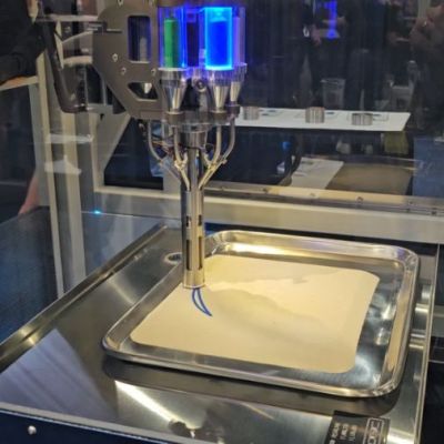
Additive Manufacturing (AM) is a field of ever-growing importance, with many startups and existing companies seeking to either improve on existing AM technologies or market new approaches. At the RAPID + TCT 2024 tradeshow it seems that we got two more new AM approaches to keep an eye on to see how they develop. These are powder-based Hot Isostatic Pressing (HIP) by Grid Logic and centrifugal 3D printing by Fugo Precision.

Grid Logic demo at RAPID + TCT 2024. (Credit: Ian Wright)

Grid Logic’s HIP uses binder-less powders in sealed containers that are compressed and deposited into a HIP can according to the design being printed, followed by the HIP process. This is a common post-processing step outside of AM as well, but here HIP is used as the primary method in what seems like a budget version of typical powder sintering AM printers. Doubtlessly it won’t be ‘hobbyist cheap’, but it promises to allow for printing ceramic and metal parts with minimal wasted powder, which is a major concern with current powder-based sintering printers.

While Grid Logic’s approach is relatively conservative, Fugo’s Model A printer using centrifugal printing is definitely trying to distinguish itself. It uses 20 lasers which are claimed to achieve 30 µm accuracy in all directions with a speed of 1 mm/minute. It competes with SLA printers, which also means that it works with photopolymers, but rather than messing with FEP film and pesky Earth gravity, it uses a spinning drum to create its own gravitational parameters, along with a built-in parts cleaning and curing system. They claim that this method requires 50% fewer supports while printing much faster than competing commercial SLA printers.

Even if not immediately relevant to AM enthusiasts, it’s good to see new ideas being tried in the hope that they will make AM better for all of us.

This Vintage Computing Device Is No Baby Food

Today, if you want a computer for a particular task, you go shopping. But in the early days of computing, exotic applications needed custom computers. What’s more is that with the expense of computers, you likely got one made that fit exactly what you needed and no more. That led to many oddball one-off or nearly one-off computers during that time frame. Same for peripheral devices — you built what you had to and you left the rest on the drafting table. [Vintage Geek] got his hands on what appears to be one of them: the Gerber Scientific 6200.

While Gerber Scientific is still around, we’ve never heard of the 6200. Based on the serial number, we would guess at least 62 of them were made and this one has an interesting backstory of living in someone’s home who worked at the Pentagon. We presume the tapes were erased before it was sold!

Design-wise, it is pretty standard stuff. A 19-inch rack, a standard tape drive from Kennedy, a power supply, and some cards. The box takes 240 V, so the computer didn’t get powered up, but an examination of the inside looked like this really was a one-off with handwritten labels on masking tape.

We couldn’t tell for sure if the device was a computer itself, or just a tape drive and maybe plotter interface for another computer. If you know anything about this device, we are sure [Vintage Geek] would like to hear from you.

If this does turn out to have a CPU onboard, we’d bet it is bit sliced. If you have a 9-track tape machine, you may have to make your own tapes soon.

Continue reading “This Vintage Computing Device Is No Baby Food”