A MIDI Sequencer To Be Proud Of

MIDI sequencers are surprisingly expensive, making them an excellent target for [RH Electronics] who has created a sixteen-step device. It supports up to eight playable parts per step, which can be either MIDI or drum triggers.

The case and front panel are built to a very high standard, and on a piece of stripboard within lies an ATmega644 which does all the MIDI work, an ATmega328 that runs the many LEDs, and an ATtiny85 that reads the front panel buttons. The whole is kept in sync by a timer on the 644 set to produce the required MIDI clock. There is an LCD display too, which carries the status and programming interface.

You can see the result in the video below the break, in which the sequencer is put through its paces alongside a tantalising glimpse of a matching synthesiser. Is this another project, or a commercial device on which Google fails us when we try to find it? Meanwhile this is certainly not the first MIDI sequencer we’ve brought you here at Hackaday, this Arduino one is another example of several also using Atmel parts.

Continue reading “A MIDI Sequencer To Be Proud Of”

Double The Resolution, From An Arduino ADC

Analog-to-digital converters, or ADCs, are somewhat monolithic devices for most users, a black box that you ask nicely for the value on its input, and receive a number in return. For most readers, they will be built into whatever microcontroller is their platform of choice, and their resolution will be immutable, set by whatever circuitry is included upon the die. There are a few tricks that can be employed to get a bit more from a stock ADC though, and [Neris] has taken a look at a couple of them.

The first circuit doubles the resolution of an ADC, in this case, that of the Atmel chip in an Arduino, by converting its output from an integer to a signed integer. It performs this task with a precision rectifier, rectifying around a zero-crossing point half-way through the range of the analog value to be read and supplying a sign bit to the Arduino. The Arduino measures the rectified analog value to an integer, and applies the appropriate sign from the supplied bit value.

The second circuit takes a variation on the same technique but with two ADCs instead of one. A pair of PIC chips are used with their voltage references stacked one above the other, by taking both readings in combination a result with double the resolution can be derived.

You might ask why bother with these techniques. After all, there are plenty of higher-resolution ADCs on the market. But they’re useful techniques to know, should you ever need to extract the proverbial quart from a pint pot.

If ADCs are a mystery to you, you’re in luck. [Bil Herd] gave us a comprehensive introduction to the subject.

Dissecting The AVR DebugWire

Anyone who’s ever written more than a dozen or so lines of code knows that debugging is a part of life in our world. Anyone who’s written code for microcontrollers knows that physical debugging is a part of our life as well. Atmel processors use a serial communications protocol called debugWire, which is a simpler version of JTAG and allows full read/write access to all registers and allows one to single step, break, etc. [Nerd Ralph], a prominent fixture here at Hackaday has dug into the AVR debugWire protocol and enlightened us with some valuable information.

While the protocol side of debugWire is a mostly-solved problem, the physical layer was giving him trouble. He started with a diode, and then went through a couple resistors and other components to interface with the debugWire pin on the AVR microcontroller, doing most of the troubleshooting work so now you don’t have to. He notes that interface components might need to be tailored to specific USB-TTL adapters, so keep that in mind if you care to delve into working with debugWire yourself.

We’re no strangers to debugging techniques here at Hackaday. As always, be sure to let us know if you run across any new techniques or try anything new yourself!

Audio Hacking With The ESP8266

If you study the specifications of the ESP8266 WiFi-enabled microcontroller, you will notice that it features an I2S audio interface. This is a high-speed serial port designed to deliver 16-bit audio data in a standard format, and has its origins in consumer audio products such as CD players. It would be usual to attach a dedicated DAC to an I2S interface to produce audio, but [Jan Ostman]’s synthesiser projects eschew that approach, and instead do the job in software. His I2S interface pushes out a pulse density modulated data stream in the same manner as a 1-bit DAC, meaning that the only external components required to produce audio are a simple low-pass filter. He’s posted a video of the synth in action, which we’ve placed below the break.

The example he gives us is a basic clone of a Roland 909 drum machine, and he takes us through the code with extensive examples including MIDI. He’s using the Wemos D1 Mini board, but the same could be replicated with many other ESP8266 platforms.

We’ve featured [Jan]’s work many times before, from his minimalist Atmel-based devices through to small but perfectly-formed complete instruments.

Continue reading “Audio Hacking With The ESP8266”

Only Mechanical Relays Will Do For Automated Hi-Fi Audio Source Switching

If you are a devotee of audiophile-quality analogue hi-fi, switching between sources simply can not be done through a solid-state device. Only physical switches will do because they come without the risk of extra noise or distortion that their silicon equivalents might bring.

That is the philosophy that lies behind [Skrodahl]’s relay-based audio switching board, which boasts 5 high-quality relays each handling a stereo input, with their control passed either to a rotary switch or to an ESP32 module. The ground connections on audio and switching sides are isolated from each other to avoid transient noise finding its way to the speakers.

You might think that an audio switching board is a very simple device indeed and thus not worthy of Hackaday’s attention, but it’s surprisingly easy to make a mess of a module like this one and they have put in some effort to avoid the pitfalls. The metal-can version of the switching transistors seems a little overkill, but fancy audio is a funny business.

If the ESP isn’t your bag, we’ve brought you another relay based audio switcher in the past that used an Atmel chip.

Microchip Acquires Microsemi For $8.35B

Microchip has acquired Microsemi for $8.35 Billion dollars. Rumors of this acquisition were floating around earlier this week, but now the deal is done.

This acquisition is the latest in a years-long process of consolidation in the silicon industry. Previously, Broadcom attempted a hostile takeover of Qualcomm for One… Hundred… Billion dollarsLattice would have been bought if the deal wasn’t shut down for national security concerns. Of course, Microchip bought Atmel in a deal likened to the fall of Constantinople, NXP and Freescale merged, Intel bought Altera, Linear and Analog are one, and On Semiconductor acquired Fairchild.

With the acquisition of Microsemi, Microchip will be looking to add a few interesting components and capabilities to their portfolio. In contrast to Microchip’s portfolio, you won’t find many Microsemi parts on a hacker’s workbench; they’re dealing with stuff like optical networking and avionics. Closer to home, they have a large line of FPGAs and some nice frequency synthesizers.

Of course, there are slightly cooler components in Microsemi’s portfolio. If you’ve ever wanted a rad-tolerant telemetry controller for reaction wheels and thruster assemblies, they’ve got your back. Just connect that to Microchip’s rad-hard Arduino and you have a complete satellite built from Microchip parts.

New Part Day: ATMegas With Programmable Logic

Since Microchip acquired Atmel, the fields of battle have fallen silent. The Crusaders have returned home, or have been driven into the sea. The great microcontroller holy war is over.

As with any acquisition, there is bound to be some crossover between two product lines. Both Atmel’s AVR platform and Microchip’s PICs have their adherents, and now we’re beginning to see some crossover in the weird and wonderful circuitry and design that goes into your favorite microcontroller, whatever that might be. The newest part from Microchip is an ATMega with a feature usually found in PICs. This is a Core Independent Peripheral. What is it? Well, it’s kinda like a CPLD stuck in a chip, and it’s going to be in the new Arduino board.

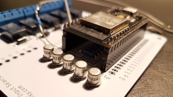
The ATMega4809 is the latest in a long line of ATMegas, and has the features you would usually expect as the latest 8-bit AVR. It runs at 20MHz, has 48 K of Flash, 6 K of SRAM, and comes in a 48-pin QFN and TQFP packages. So far, everything is what you would expect. What’s the new hotness? It’s a Core Independent Peripheral in the form of Configurable Custom Logic (CCL) that offloads simple tasks to hardware instead of mucking around in software.

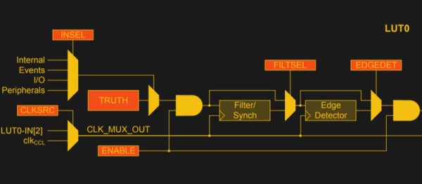
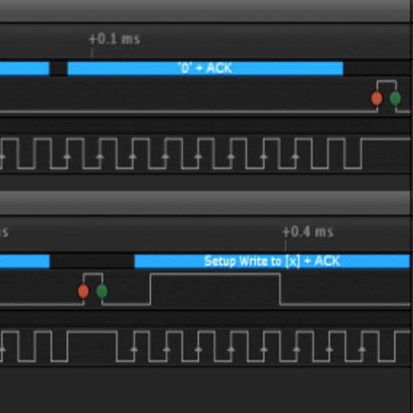
So, what can you do with Configurable Custom Logic? There’s an application note for that. The CCL is effectively a look-up table with three inputs. These inputs can be connected to I/O pins, driven from the analog comparator, timer, UART, SPI bus, or driven from internal events. The look-up table can be configured as a three-input logic gate, and the output of the gate heads out to the rest of the microcontroller die. Basically, it’s a tiny bit of programmable glue logic. In the application note, Microchip provided an example of debouncing a switch using the CCL. It’s a simple enough example, and it’ll work, but there are a whole host of opportunities and possibilities here.

Additionally, the ATMega4809, “has been selected to be the on-board microcontroller of a next-generation Arduino board” according to the press release I received. We’re looking forward to that new hardware, and of course a few libraries that make use of this tiny bit of custom programmable logic.