For those who are not into prog rock in the 70s or old radio shows from the 40s, the Theremin may be an unfamiliar musical instrument. As a purely electronic device, it’s well outside the realm of conventional musical instruments. Two radio antennas detect the position of the musician’s hands to make a unique sound traditionally associated with eeriness or science fiction.
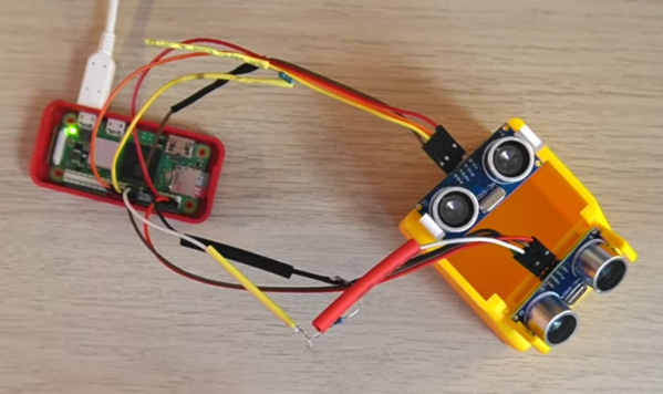
Normally a set of filters and amplifiers are used to build this instrument but this build instead replaces almost everything with a Raspberry Pi Zero 2, and instead of radio antennas to detect the position of the musician’s hands a set of two HC-SR04 distance sensors are used instead. With the processing power available from the Pi, the modernized instrument is able to output MIDI as well which makes this instrument easily able to interface with programs like GarageBand or any other MIDI-capable software.
The project build is split into two videos, the second of which is linked below. The project code is also available on the project’s GitHub page, so anyone with the Pi and other equipment available can easily start experimenting with this esoteric and often overlooked musical instrument. It’s been around for over 100 years now, and its offshoots (including this build) are as varied as the sounds they can produce.