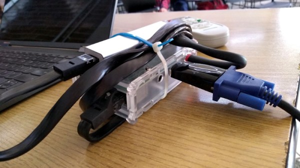
A Raspberry Pi next to a small circuit board

An Inexpensive FM Receiver For The Raspberry Pi

At this point, there are no shortage of impressive hacks for the Raspberry Pi. [Dilshan Jayakody] recently documented his experience in designing and building an inexpensive FM Stereo Receiver for the Pi platform, and the results are impressive.

Quite a few FM receiver projects center around the RDA5807 or TEA5767 ICs, however [Dilshan] has used the QN8035 by Quintic Corporation in his build. A handful of discrete components on a pleasing single-sided PCB is all that is needed to interface the QN8035 with the Pi’s I2C bus.

After demonstrating that the FM tuner could be, well, tuned at the command line, [Dilshan] then coded a smart looking GUI application that makes tuning a breeze. The software allows the listener to manually and automatically scan through FM stations, decode program service data, control the volume, and display the RSSI and SNR readings from the tuner.

As we reported earlier, FM radio is on a slow decline into obsolescence. This latest project isn’t aiming to break new ground, however its simplicity and inexpensive components are the perfect combination for beginner hackers and radio enthusiasts alike. More details can be found over on Hackaday.io. The schematic, source code and bill of materials can be found on GitHub.

Continue reading “An Inexpensive FM Receiver For The Raspberry Pi”

MC68k SBC with a monitor, keyboard and mouse

Motorola 68000 SBC Runs Again With A Raspberry Pi On Top

Single-board computers have been around a long time: today you might be using a Raspberry Pi, an Arduino, or an ESP32, but three decades ago you might find yourself programming a KIM-1, an Intel SDK-85, or a Motorola 68000 Educational Computer Board. These kind of boards were usually made by processor manufacturers to show off their latest chips and to train engineers who might use these chips in their designs.

[Adam PodstawczyƄski] found himself trying to operate one of these Motorola ECBs from 1981. This board contains a 68000 CPU (as used in several Macintoshes and Amigas), 32 kB of RAM, and a ROM program called TUTOR. Lacking any keyboard or monitor connections, the only way to communicate with this system is a pair of serial ports. [Adam] decided to make the board more accessible by adding a Raspberry Pi extended with an RS232 Hat. This add-on board comes with two serial ports supporting the +/- 12 V signal levels used in older equipment.

It took several hours of experimenting, debugging, and reading the extensive ECB documentation to set up a reliable connection; as it turns out, the serial ports can operate in different modes depending on the state of the handshake lines. When the Pi’s serial ports were finally set up in the right mode, the old computer started to respond to commands entered in the terminal window. The audio interface, meant for recording programs on tape, proved more difficult to operate reliably, possibly due to deteriorating capacitors. This was not a great issue, because the ECB’s second serial port could also be used to save and load programs directly into its memory.

With the serial connections working, [Adam] then turned to the aesthetics of his setup and decided to make a simple case out of laser-cut acrylic and metal spacers. Custom ribbon cables for the serial ports and an ATX break-out board for power connections completed the project, and the 40-year-old educational computer is now ready to educate its new owner on all the finer points of 68000 programming. In the video (embedded after the break) he shows the whole process of getting the ECB up and running.

[Adam] made a similarly clever setup with a Commodore 64 and an Arduino earlier. [Jeff Tranter] recreated a similar 68000 development board from scratch. And a few years ago we even featured our own custom-built 68k computer.

Continue reading “Motorola 68000 SBC Runs Again With A Raspberry Pi On Top”

Raspberry Pi And ESP32-S2 Team Up For MutantC_V4

Back in 2019 we first came across the mutantC, an open source 3D printable Raspberry Pi handheld created by [rahmanshaber] that took more than a little inspiration from Sony’s VAIO ultra-mobile PCs (UMPCs) from the early 2000s. It was an impressive first effort, but it clearly had a long way to go before it could really be a practical mobile device.

Well after two years of development and three iterative versions of this Linux powered QWERTY slider, [rahmanshaber] is ready to show off the new and improved mutantC_v4. Outwardly it looks quite similar to the original version, with the notable addition of a tiny thumbstick and a pair of programmable buttons on the right side that can be used for input in addition to the touch screen. But inside it’s a whole other story, with so many changes and improvements that we hardly even know where to start.

Inside the mutantC_v4, showing off the ESP32-S2

Probably the most notable improvement is the addition of an ESP32-S2, specifically a bare ESP-12K module, to the main PCB. Previous versions of the hardware used an Arduino Pro Micro to interface with all the hardware, but the added horsepower of the ESP32 should come in handy with the array of sensors, controls, and NeoPixels that [rahmanshaber] has tasked the chip with. There’s even a buzzer and a coin-style vibration motor in there to provide some feedback to the user. While the board has changed significantly, it still retains compatibility with the Pi Zero, 2, 3, and 4.

Another notable addition is the expansion connector on the bottom of the handheld that has pins for I2C, UART, and 3.3 V. In the video below, [rahmanshaber] mentions that this feature was previously implemented with a standard 2×6 female header block, but is now using a far slimmer female USB-C port. We do wonder if it’s not a bit confusing to have this faux-USB port right next to the real one that’s actually used to charge the system, but with such cramped quarters occasionally you’ve got to make some tough decisions like that.

It’s quite inspiring to see how [rahmanshaber] has honed his skills since releasing the first version of the mutantC. The 3D printed parts and PCBs have matured considerably over the last two years, showing how quickly a dedicated hobbyist can advance their abilities. The most recent version has been entered in the 2021 Hackaday Prize. But the show isn’t over yet, as we hear v5 of this impressive handheld may tackle the Raspberry Pi 4 Compute Module.

Continue reading “Raspberry Pi And ESP32-S2 Team Up For MutantC_V4”

Psion Organiser with a Pico memory pack.

Proto-PDA Regains Its Memory With The Help Of A Raspberry Pi Pico

Remember the Psion Organiser? If you do, chances are you were an early adopter, as the 8-bit pocket computer had its heyday in the mid-1980s. Things have come a long way since then, of course, but just how far is illustrated nicely by the fact that a Raspberry Pi Pico can stand in for the Psion’s original memory packs.

Like many of the early attempts at putting a computer in your pocket, the Psion II had removable modules, which were dubbed “Datapaks”. The earliest versions of the Datapaks were little more than an EPROM chip on a small PCB, and the technical limitations of the day plus the quirky way of addressing the memory made it possible for [Amen] to mimic a Datapak using a modern microcontroller.

The first version was a breakout board that extended out of the Datapak slot significantly, with a Pico, OLED display, SD card slot, and a bunch of pushbuttons. That prototype proved that the Pico was indeed fast enough to fool the Psion into thinking a legit Datapak was plugged in. [Amen] later refined the design by making a board that stuffs everything into the Datapak slot, with the exception of the OLED which still dangles out where it can be seen. He puts the faux memory to the test in the video below.

It’s great to see groundbreaking tech of yesteryear like the Psion being taken care of and returned to use. We’ve seen others try before; here’s a hack that uses a Pi to connect a Psion Organiser to the internet through its RS-232 serial port.

Continue reading “Proto-PDA Regains Its Memory With The Help Of A Raspberry Pi Pico”

magicBlueSmoke-piStick-featured

How Do You Make A Raspberry Pi On A Stick?

We agree with [magic-blue-smoke] that one of the only things more fun than a standard Raspberry Pi 4 is the Compute Module form factor. If they are not destined to be embedded in a system, these need a breakout board to be useful. Each can be customized with a myriad board shapes and ports, and that’s where the real fun starts. We’ve already seen projects that include custom carrier boards in everything from a 3D Printer to a NAS and one that shows we can build a single-sided board at home complete with high-speed ports.

[magic blue smoke] used this ability to customize the breakout board as an opportunity to create a hackable media player “stick” with the Raspberry Pi built-in. We love that this Raspberry Pi CM4 TV Stick eliminates all the adapters and cables usually required to connect a Pi’s fiddly micro HDMI ports to a display and has heat sinks and an IR receiver to boot. Like a consumer media player HDMI stick, all you need to add is power. Continue reading “How Do You Make A Raspberry Pi On A Stick?”

Raspberry Pi Powered Standing Desk Rises To New Heights

Like many office workers, [David Kong] found himself the lucky recipient of a motorized sit-stand desk. Also like most office workers with such a desk, he found himself mostly sitting. Reminders on his phone did little to change habits and [David] resolved to automate his desk to rise on a schedule.

the control board for a poppin sit stand desk

Taking off the front panel of the control box required a few screws and [David] was delighted to find some testing pins right on the PCB.By connecting the right pins together, he could simulate any button being pressed. A Toshiba TLP222A solid-state relay made it simple to connect the pins together, the next step was triggering the relay on some sort of timer.

Speaking of timers, the oft-lauded 555 timer was considered. However, the length of time desired wasn’t as well suited for the 555, and the appeal of just tweaking a file to adjust the interval was tempting. Going to the other end of the spectrum, [David] had a Raspberry Pi zero laying around he had been meaning to play with.

After soldering the relay to pin 17 and writing a quick 10 line python script that is executed on startup, [David] had a working solution that could be taped to the underside of the desk, out of sight. Rather than being on a fixed timer, the desk raises every 45 to 60 minutes. The impact on his life has been wonderful, which was the goal of this particular project. It’s been a few months and he hasn’t had to tweak or fix anything. Is a whole 64-bit multicore processor a bit of an overkill for toggling a pin every hour or so? Yes. But we can’t really fault him for reaching for what was already lying around. The results speak for themselves.

Perhaps this would be something you would incorporate when you’re building your own standing desk?

Raspberry Pi Real-Time HAT

New Part Day: Raspberry Pi HAT For IEEE1588 Precision Time Protocol

The new Real-Time HAT by InnoRoute adds IEEE1588 PTP support in hardware to a Raspberry Pi 4 nestled beneath. Based around a Xilinx Artix-7 FPGA and a handful of gigabit Ethernet PHY devices, the HAT acts as network-passthrough, adding accurate time-stamps to egress (outgoing) packets and stripping time-stamps from the ingress (incoming) side.

This hardware time-stamping involves re-writing Ethernet packets on-the-fly using specialised network hardware which the Raspberry Pi does not have. Yes, there are software-only 1588 stacks, but they can only get down to 10s of microsecond resolutions, unlike a hardware approach which can get down to 10s of nanoseconds.

1588 is used heavily for applications such as telecoms infrastructure, factory equipment control and anything requiring synchronisation of data-consuming or data-producing devices. CERN makes very heavy use of 1588 for its enormous arrays of sensors and control equipment, for all the LHC experiments. This is the WhiteRabbit System, presumably named after the time-obsessed white rabbit of Alice In Wonderland fame. So, if you have a large installation and a need for precisely controlling when stuff happens across it, this may be just the thing you’re looking for.

IEEE1588 PTP Synchronisation

The PTP client and master device ping a few messages back and forth between themselves, with the network time-stamper recording the precise moment a packet crosses the interface. These time-stamps are recorded with the local clock. This is important. From these measurements, the time-of-flight of the packet and offset of the local clock from the remote clock may be calculated and corrected for. In this way each client node (the hat) in the network will have the same idea of current time, and hence all network packets flowing through the whole network can be synchronised.

The beauty of the system is that the network switches, wiring and all that common infrastructure don’t need to speak 1588 nor have any other special features, they just need to pass along the packets, ideally with a consistent delay.

The Real-Time HAT configures its FPGA via SPI, straight from Raspberry Pi OS, with multiple applications possible, just by a change on the command line. It is possible to upload custom bitstreams, allowing the HAT to be used as a general purpose FPGA dev board should you wish to do so. It even stacks with the official PoE HAT, which makes it even more useful for hanging sensors on the end of a single wire.

Of course, if your needs are somewhat simpler and smaller in scale than a Swiss city, you could just hack a GPS clock source into a Raspberry Pi with a little soldering and call it a day.