Hackers, makers, and engineers have been hacking on robot projects since the era of clockwork mechanics. Any robot is a cool project, but there is something particularly attractive about small ones. Maybe it’s the skill required to assemble them, or perhaps it’s the low-cost. Either way, there are lots of palm-sized robot projects on Hackaday.io. This week on the Hacklet, we’re going to highlight a few of them!
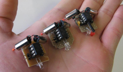 We start with the granddaddy of them all, [shlonkin] and Tiny robot family. [Shlonkin] built line following robots that can hide under a US half-dollar coin. The robots are simple circuits – an ATtiny85 with an LED and pair of phototransistors. The code is provided both in Arduino’s wiring, and in straight C++. Two coreless motors, normally used in cell phones vibrators or quadcopters, provide the locomotion. These robots only know one thing – moving forward and following a line. They do it well though! We love this project so much that we hosted a tiny robot workshop at the 10th anniversary back in 2014.
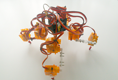 When it comes to tiny walking robots, [Radomir Dopieralski] is the king. Many of his projects are small biped, quadruped, or even hexapod robots. He’s done things with 9 gram nano servos that we thought were impossible. Tote, an affordable spider robot, is his latest creation. Tote is a four-legged bot utilizing 12 9 gram servos. [Radomir] created a custom PCB for Tote, which acts as a carrier for its Arduino Pro Mini Brain. This robot is easily expandable – [Radomir] has experimented with the Teensy 3 series as well. Controlling the robot can be anything from an ESP8266 to an infrared remote control.
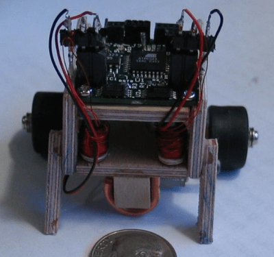 [Alan Kilian] may well have the ultimate tease project with Hand-wound inductors for a tiny robot. [Alan] was using some tiny GM-10 motors on his micro-bot. The motors didn’t have inductance for the locked-antiphase drive controller. His solution was to wind some coils to provide a bit of added inductance. The mod worked, current consumption dropped from 116 ma to about 6 ma. We want to know more about that ‘bot though! It’s controlled by a Megabitty, [Monty Goodson’s] ATmega8 controller board from sometime around 2003. The lilliputian board has been very popular with the nano sumo crowd. Other than the controller, motors, and the plywood frame, [Alan] has left us guessing about his robot. If you see him, tell [Alan] to give us more info on his micro robot’s design and construction!
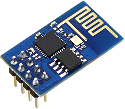
 [Ccates] jumped on the tiny robot bandwagon with Tiny wi-fi robot. Rather than go with an Arduino for control, [Ccates] grabbed the popular ESP-8266 WiFi module. The construction of the bot is inspired by [shlonkin’s] tiny robot family up above. This bot is controlled by the Xtensa processor embedded in the ESP-8266. Since it only drives forward, it only takes two GPIO pins to control the transistors driving the motors. Even the diminutive ESP-01 module has enough I/O for that. We’d love see some sensors and a full H-bridge on this micro beastie!
If you want to see more palm-sized robot projects, check out our new tiny robot projects list! These ‘bots are small, so I may have missed yours. If that’s the case, don’t be shy, just drop me a message on Hackaday.io. That’s it for this week’s Hacklet. As always, see you next week. Same hack time, same hack channel, bringing you the best of Hackaday.io!

 When we first heard about it a few weeks ago, we knew the ESP8266 UART to WiFi module was a special beast. It was cheap, gave every microcontroller the ability to connect to a WiFi network, and could – possibly – be programmed itself, turning this little module into a complete Internet of Things solution. The only thing preventing the last feature from being realized was the lack of compiler support. This has now changed. The officially unofficial ESP8266 community forums