IGY: The Year We All Got Along

If you are a Steely Dan fan, you might know the Donald Fagen song, “IGY.” In it, Fagen sings about a rosy future with high-speed undersea rail, solar power, giant computers making life better, and spandex jackets. Since that song was on the 1982 album Nightfly, it is already too old for some people to remember, but the title goes back even further: the International Geophysical Year which was actually a little longer than a year in 1957 and 1958. The year was a concerted effort by 67 countries to further mankind’s knowledge of the Earth. It was successful,  and was big news in its day, although not much remembered now.

The real origin dates back to even earlier. In 1882 and 1932 there were International Polar Years dedicated to researching the polar regions of the Earth. In a way, it makes sense to do this. Why should 60 or more countries each mount difficult, dangerous, and expensive expeditions to such a hostile environment? However, instead of a third polar year, James Van Allen (who has a famous belt) and some other scientists felt that advances in many fields made it the right time to study geophysics. From the scientific point of view, the IGY coincided with the solar activity cycle maximum. But there were other forces at play, too.

Continue reading “IGY: The Year We All Got Along”

Low Parts Count ARM SDR

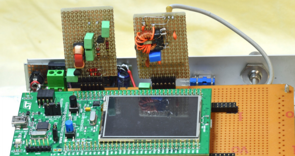
[Alberto di Bene] wanted to build an SDR for relatively low frequencies. Usually, you’d start with some front end to get the radio frequency signal down where you can work with it. But [Alberto] practically just fed an antenna into an STM32F429 Discovery board and did all the radio processing in the onboard ARM chip.

There is a little more to it than that, but only a little. If you open the PDF file on [Alberto’s] site, you’ll see there is a simple front end filter (a transformer, along with a few capacitors and inductors). This low pass filter prevents high frequencies from reaching the ARM processor’s analog to digital converter. In addition, a capacitor and a couple of resistors ensure the converter only sees positive voltages.

The CPU digitizes the incoming signal and processes it, demodulating several different types of radio transmission. The recovered audio is sent through the onboard digital to analog converter.

In addition to an input filter, the output also needs a filter to prevent high frequencies from reaching the speaker. Unlike the input filter, this one is a bit more complicated. The inductors needed for a passive filter were too large to be practical, so the output filter is an active one with a few transistors. The only other external circuitry is the power supply for the Discovery board.

The document does a great job of explaining the rationale behind the design choices and how the whole system works. It also includes simulations of both analog and digital filters used in the design.

This is really bare metal SDR and reading the code is educational. However, if you want to start with something simpler, consider GNU Radio and either an SDRPlay or a cheap RTL-SDR dongle.


Mac SE

Viewing A Macintosh SE’s Video On A Modern Computer

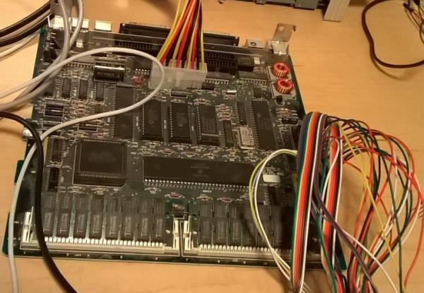
[Bbraun] has an old Macintosh SE computer. He was looking for a way to view the video output from the SE on a newer, modern computer. He ended up working out a pretty clever solution using a stm32f4discovery board.

First, the SE’s logic board was removed from its case and placed onto a desk for easier access. The discovery board was then hooked up to the SE’s processor direct slot (PDS) using normal jumper wires. The discovery board acts as a USB COM port on a newer Mac OSX computer. The discovery board watches the SE for writes to video memory. When it sees that the R/W pin goes low, it knows that a write is occurring. It then waits for /AS to go low, which indicates that an address is on the bus. The discovery board reads the address and verifies that it falls within the range of the video frame buffer. If it does, then the discovery board writes a copy of the data to a local buffer.

The OSX computer runs a simple app that can make a request to the discovery board via USB. When the board receives the request, it sends its local frame buffer data over the USB connection and back to the host. The OSX computer then displays that data in a window using CGImage. The demo video below was captured using this technique. Continue reading “Viewing A Macintosh SE’s Video On A Modern Computer”

Impressive Dev Boards For Your STM32 Dev Boards

stm32-discovery-breakout-boards

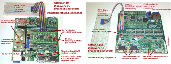
It seems there are a lot of people who have the same complaint about the STM32 Discovery boards; it can be difficult to add external hardware to them. Don’t get us wrong, we appreciate all of the pins being broken out (as opposed to the Stellaris Launchpad which we think has too few available). Here’s [Scot Kornak’s] solution to the problem. He created three different baseboards which the STM32 Discovery plugs into. Each is for a different model of dev board: the VL, F3, and F4. But he also thinks the baseboard we saw in this other project is a good choice for an F4 solution.

These large PCB add-ons bring functionality in two different ways. The first is by using expandable ports for drop in modules like serial communications connectors or Analog/SPI/I2C modules. For us, the second method is the most desirable. He routes each GPIO port to a 2×8 header and uses IDC cables (rainbow cable in these images) to connect them to a breadboard. Seeing this makes us wish STM had used discreet clusters of 16 pins instead of those super long dual pin headers.

UDP Between STM32-F4 Discovery Boards

stm32-f4-udp

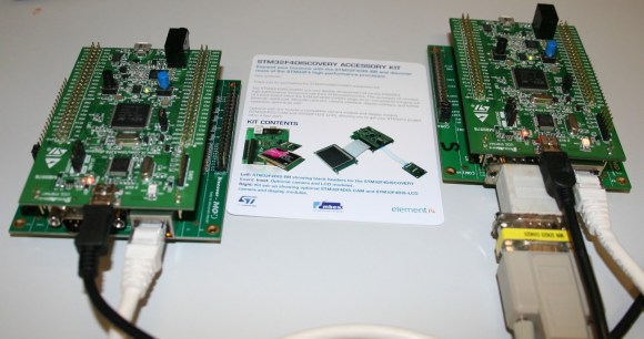
[The Backwoods Engineer] tested out a new accessory kit for the STM32-F4 Discovery board. The image above shows two boards communicating with the UDP protocol. Notice the extra PCB into which each Discovery board has been plugged. This is a third-party add-on which adds Ethernet, RS-232, SD card slot, and a connector for LCD or Camera. We’ve had one of these F4 Discovery boards on hand for a while and haven’t figured out a good way to connect external hardware to the huge dual pin-headers. This doesn’t solve the problem — the base board also includes dual headers to break-out all the pins — but having Ethernet, serial, and SD certainly reduces the need to add all that much more. The other drawback to the hardware is that the sample firmware is targeted at the IAR Embedded Workbench which is neither free, nor in the realm of affordable for hobbyists.

The NIC used on the baseboard has auto-crossover capabilities so the boards were connected using a regular Cat6 patch cable. This example has the boards constantly sending UDP packets with the module on the right reporting status information to a terminal via the serial connection.

In-depth Comparison At STM32 F3 And F4 Discovery Boards

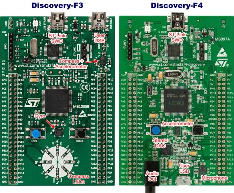
The STM32 F3 and F4 Discovery boards have been around for a while now. We’ve looked at both separately and they’re impressive dev boards for the price. Now can get a closer look at each from this in-depth comparison of the two Cortex-M4 development tools.

To start off, both of the boards have the same size and footprint (there are two dual-row pin headers which break out the connections to the ARM chip). Fundamentally the F3 and F4 chips have a different level of features, but the boards themselves are aimed at different applications as well. The F3 series of microcontrollers looks to be more affordable than the F4, containing less program memory, no Ethernet capability, and only one USB port. But both have hardware floating-point abilities and they’re blazing fast. The boards offer a MEMS accelerometer for prototyping. But the Discovery-F3 also contains a gyroscope while the Discovery-F4 provides audio hardware like a microphone, and DAC.

If you want to use a Linux box to develop with these tools you might find this guide helpful.

.NET For The STM32 F4 Discovery Board

Here’s a technique that will let you use the .NET framework on an STM32 Discovery board. [Singular Engineer] was happy to learn that the .NET Micro Framework had been ported for STM32 chips. It’s doesn’t look like the port has hit a stable version yet, but these instructions will be enough to get you up and running. This lets you use managed code in the C# language to program an embedded device: the STM32 F4 Discovery board.

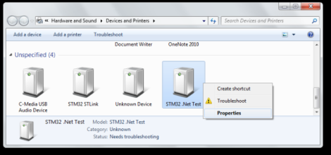
After flashing a new bootloader to the board a driver needs to be added for Windows to communicate with it. Above you can see that the board will enumerate as ‘STM32 .Net Test’. Once the driver is installed the rest of the firmware can be loaded on the board using a GUI supplied with the NETMF for STM32 package. That takes care of prepping the hardware, the rest is a painless process of configuring Visual Studio to use the board as a target. The ‘Hello World’ application then uses C# to blink an LED.