On the one hand, the original Apple II has been copied over and over again since at least the early 80s, so maybe this hack is old hat to the greybeards around here. On the other hand, this is the year 2026. When Apple released it back in 1977, who could have predicted people would still be building these things nearly five decades later?
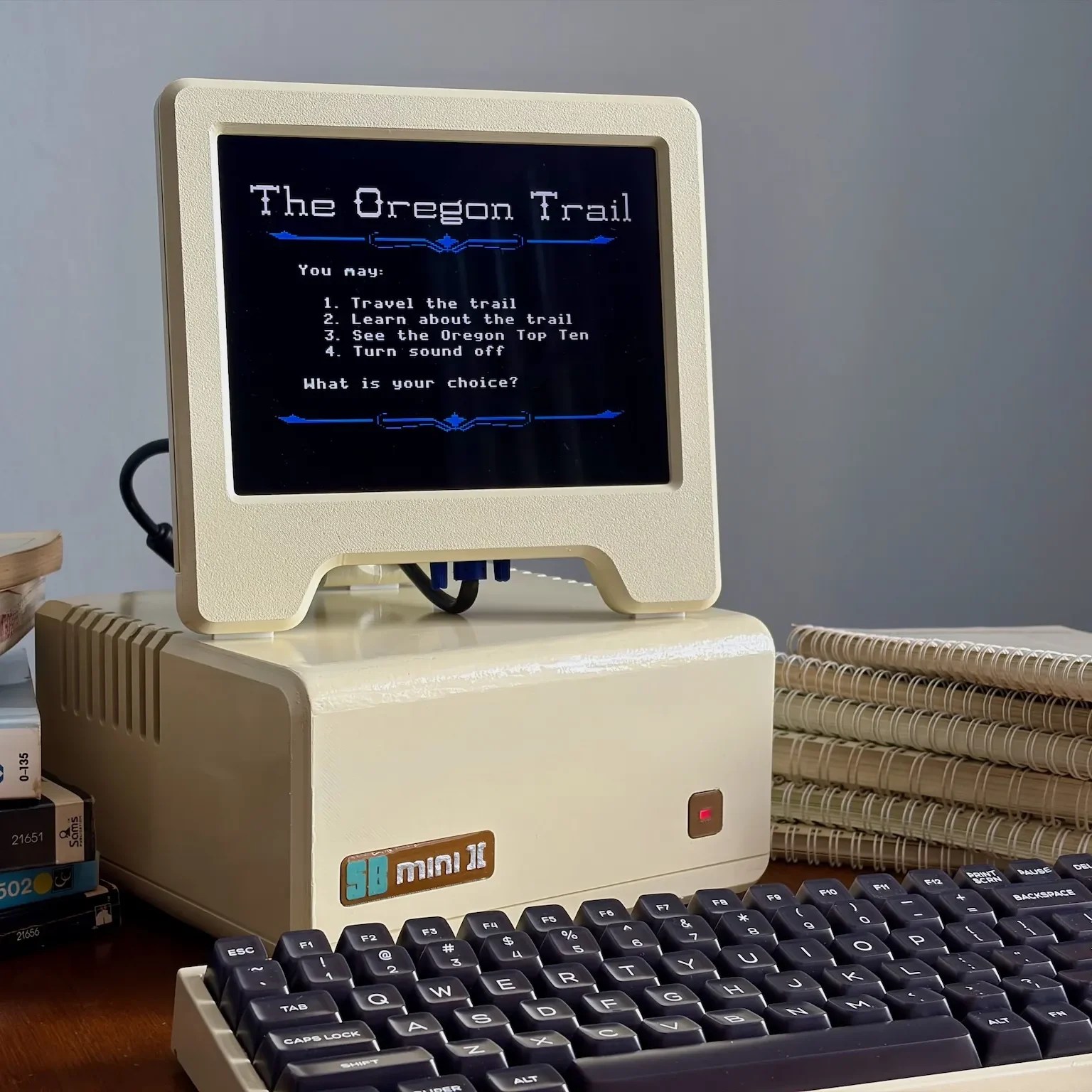
In that sense, a homebrew Apple II in the current year is pretty remarkable. It’s a really well done project by [simonboak], nicely open sourced with a case to match, so is worth looking at on its own merits.
Unlike the later models, the original Apple II only used commercially available ICs, making it an easy target for recreation. No FPGAs required, just good old-fashioned DIPs. OK, these are modern CMOS versions of the chips, but other than that, the biggest concession to modernity is space on the board for a Raspberry Pi Pico to allow for connecting a USB keyboard.
The accompanying blog post lists some other differences from 1977’s favorite home computer: SRAM vs DRAM — because you know the Woz would have used it if he could — and omitting the composite video circuitry in favor a late-model VGA card. There’s no need for the composite output since he’s eschewing the period-appropriate CRT for a retro-styled LCD monitor, which is also 3D printed and available on Printables. It’s crazy to think that the Apple II family lived long enough not only to see the dawn of VGA but also well into its sunset.
If a homebuilt Apple ][ doesn’t impress, what about a PC-compatible circa 1995?