Genetic Algorithm Programmer Gets Functions

[Kory] has been writing genetic algorithms for a few months now. This in itself isn’t anything unique or exceptional, except for what he’s getting these genetic algorithms to do. [Kory] has been using genetic algorithms to write programs in Brainfuck. Yes, it’s a computer programming a computer. Be thankful Skynet is 18 years late.

When we first saw [Kory]’s work, he had programmed a computer to write and run its own programs in Brainfuck. Although the name of the language [Kory] chose could use some work, it’s actually the ideal language for computer-generated programs. With only eight commands, each consisting of a single character, it greatly reduces the overhead of what any genetic algorithm must produce and what a fitness function must evaluate.

There was one shortcoming to [Kory]’s initial efforts: functions. It’s relatively easy to get a program to say Hello World, but to do something complex, you’re going to need something like a macro or a function. Brainfuck, it its most simple form, doesn’t support functions. This throws a wrench in [Kory]’s plan to have his computer programming computer grow smarter and get over local minima in its genetic algorithms.

The solution to this problem was the creation of a new dialect of Brainfuck [Kory] calls BrainPlus. This takes the best parts of Extended Brainfuck and adds a command that basically serves as a break statement.

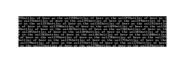
With this, [Kory]’s self programming computer can develop more complex programs. Already it has created a program to generate the first few numbers of the Fibonacci sequence. It only goes up to 233 because 255 is the maximum value for a byte, and the program itself took seven hours to generate. It does, however, work. Other programs generated with the new Brainplus functions include reciting 99 bottles on the wall and a program that multiples two values.

Even though [Kory]’s computer is spending a long time to generate these programs, given enough time, there’s really not much this program can’t do. Brainfuck, and [Kory]’s Brainplus, are Turing complete, so that given infinite memory and time it can compute anything. With the new addition of functions, it can compute anything faster.

All the code for [Kyle]’s GA is available on Github.


AVR Programmer

Inexpensive AVR Programmer Made From Five Components

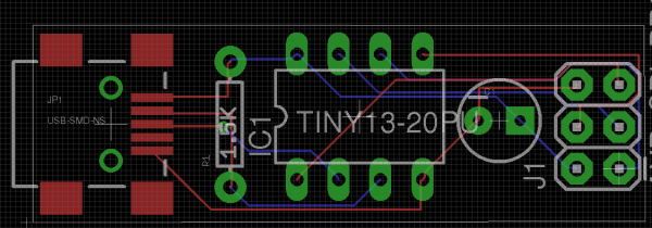
If you want to program an AVR chip as inexpensively as possible, then [Ian’s] solution might just be for you. He built an AVR programmer using only four components. This design is based on the vusbtiny AVR programmer design, with a few components left out.

[Ian’s] design leaves out two of the resistors and two diodes, leaving just four components. These include a 1.5k resistor, a small capacitor, a USB connector, a six pin header, and an ATtiny45. He admits that this may not be exactly up to USB spec, but it does work.

This is one of those projects that is really an exercise in “will it work?” more than anything else. The fact that you need to first program an AVR chip means that this wouldn’t be useful in a pinch, because you would already have to have a working programmer. Nonetheless, it’s always fun to see what can be done with as little as possible.

ISPnub – A Stand-Alone AVR In-System-Programmer Module

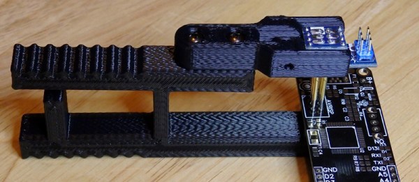
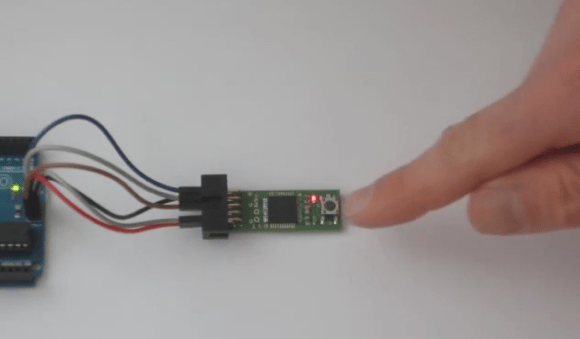
[Thomas] tipped us about his latest project: a stand-alone AVR programmer module named ISPnub. As you can see in the picture above, it is a simple circuit board composed of a main microcontroller (ATmega1284p), one button and two LEDs. Programming a target is a simple as connecting the ISPnub and pressing the button. The flashing operation success status is then shown using the green/red LED.

ISPnub gets its power from the target circuit so no external power supply is needed. It works over a wide voltage range: 1.8V to 5.5V. The module also features a programming counter which can be used to limit the number of programming cycles. A multi-platform Java tool is in charge of embedding the target flash contents with the ISPnub main firmware. The complete project is open source so you may want to check out the official GitHub repository for the firmware and the project’s page for the schematics.

Bookworm Playing Bot Tests Programmer’s OCR Skills

bookworm-bot

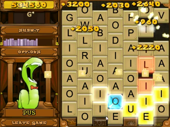
Check out this brainy bot with [Jari] whipped up to dominate the Bookworm Deluxe scoreboard. The bot runs on top of a win32 machine, pulling screenshots to see the game board and simulating mouse clicks to play. The video after the jump shows that it plays like a champ, but it took some doing to get this far and [Jari] took the time to share all of the development details.

The hardest part of writing these types of bots is recognizing the game pieces. Check out all of the animation that’s going on in the still shot above… a lot of the tiles are obscured, there are different colors, and the tiles themselves shift as the bot spells and submits each word.

After some trial and error [Jari] settled on an image pre-processor which multiplies pixel values by themselves four times, then looks at each pixel with a 1/6 threshold to produce a black and white face for each tile. From there a bit of Optical Character Recognition compares each tile to a set of known examples. This works remarkably well, leading into the logic and dictionary part of the programming challenge.

Do you think this was easier or harder than the Bejeweled Blitz bot. That one was looking for specific pixel regions, this one is basically a focused roll-your-own OCR script.


Continue reading “Bookworm Playing Bot Tests Programmer’s OCR Skills”

Tic Tac PIC Pack: A Pocket Programmer

Sure, mint tin housings are great. But you have to defend against shorts, and cutting out holes for ports and buttons is dangerous business. [Daniel] prefers plastic, and he tipped us off about a PICKit2 clone that he designed to fit inside of a tic tac box.

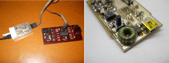
Almost all of the components were salvaged except for the microcontroller and the connectors. He wound his own inductor using the ferrite core from a CFL. [Daniel] had to make a few improvisations for this project. He didn’t have a 20MHz crystal, so he used a 12MHz crystal and tweaked the fuse bits after burning the firmware.

To save space on the board, he soldered wires to RESET, VCC, GND, PGD, and PGC to program the firmware and then removed the wires. The only trouble he had with it was more or less easily solved by replacing two transistors.

You may remember that we linked to his USBasp programmer in a mentos container a few months back. We figure [Daniel] must have some pretty fresh breath.

Overhauling An IC Programmer

Willem IC Programmer

[NeXT] needed an EPROM programmer to work with chips from vintage computers. Starting with a low cost programmer, he built this custom IC programmer to handle all of his programming needs.

The device is based on the Willem 5.0e programmer. [NeXT] was not satisfied with the device, noting that it had to be carefully isolated from metal surfaces during use and required setting many annoying jumpers.

To solve these problems, he started off by dismantling the programmer. The IC sockets were moved to a daughter board, which could be mounted cleanly into the metal enclosure. Replacing the jumpers was a bit more complicated, a combination of toggle and rotary switches were chosen to make changing settings easier.

Soldering the boards together looks like it was not an easy task, with 200 solder joints needed to connect the sockets and switches. After debugging some shorts and dead connections, [NeXT] managed to finish the 1.5 year project right before his Christmas deadline.

Automatic Bluetooth Module Programmer

automatic-bluetooth-programming

Before we dive in don’t be confused by the title. This doesn’t flash firmware to the device. But it does automate the process of setting up the Bluetooth to serial module for use in your projects.

We’re often confused by the lack of a standard way of describing these inexpensive modules. We would look at this can call it an HC-05, but we’re not sure if that’s right or not. [James Daniel] calls it a JY-MCU board. If you have a handle on the differences (or lack of) please let us know in the comments. Either way we know that these boards can be frustrating to work with. They can be found with a wide variety of different firmwares, which can make the configuration process a bit different for each.

[James’] solution connects the device to an Arduino running a sketch that he wrote. Connect the device, launch the terminal monitor in the Arduino IDE, then give it your desired settings. The sketch will poll the Bluetooth module to see what speed it is set to run at. It will then establish which firmware version the board is running, displaying this info in the terminal. It then uses that information to program the board with your desired settings.

In this case [James] is using one of the modules to drive his 3D printer without being tethered to his laptop.

Continue reading “Automatic Bluetooth Module Programmer”