The Faboratory at Yale University has set a number of stretch goals. We don’t mean that in the usual sense. They’ve been making, as you can see in the video below, clones of commercial devices that can stretch over 300%. They’ve done Ardunios and similar controllers along with sensors. The idea is to put computer circuits in flexible robots and other places where flexibility is key, like wearable electronics.
If you are interested in details, you’ll want to read the paper in Science Robotics. They take the existing PCB layout and use a laser to cut patterns in a paper mask over the stretchable substrate. They then apply oxidized gallium-indium to build conductors.
If you need an amplifier, [Hans Rosenberg] has some advice. Don’t design your own; grab cheap and tiny RF amplifier modules and put them on a PCB that fits your needs. These are the grandchildren of the old mini circuits modules that were popular among hams and RF experimenters decades ago. However, these are cheap, simple, and tiny.
You only need a handful of components to make them work, and [Hans] shows you how to make the selection and what you need to think about when laying out the PC board. Check out the video below for a very detailed deep dive.
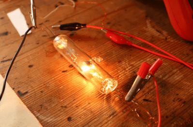
YouTuber The Science Furry has been attempting to make a split-anode magnetron and, after earlier failures, is having another crack at it. This also failed, but they’ve learned where to focus their efforts for the future, and it sure is fun to follow along.
The magnetron theory is simple enough, and we’ve covered this many times, but the split anode arrangement differs slightly from the microwave in your kitchen. The idea is to make a heated filament the cathode, so electrons are ejected from the hot surface by thermionic emission. These are forced into a spiral path using a perpendicular magnetic field. This is a result of the Lorentz force. A simple pair of magnets external to the tube is all that is needed for that. Depending on the diameter of the cavity and the gap width, a standing wave will be emitted. The anodes must be supplied with an alternating potential for this arrangement to work. This causes the electrons to ‘bunch up’ as they cross the gaps, producing the required RF oscillation. The split electrodes also allow an inductor to be added to tune the frequency of this standing wave. That is what makes this special.
Fizz, pop, ah well.
The construction starts with pre-made end seals with the tungsten wire electrode wire passing through. In the first video, they attempted to coat the cathode with barium nitrate, but this flaked off, ruining the tube. The second attempt replaces the coiled filament with a straight wire and uses a coating paste made from Barium Carbonate mixed with nitrocellulose in a bit of acetone. When heated, the nitrocellulose and the carbonate will decompose, hopefully leaving the barium coating intact. After inserting the electrode assembly into a section of a test tube and welding on the ends, the vacuum could be pulled and sealed off. After preheating the cathode, some gasses will be emitted into the vacuum, which is then adsorbed into a nearby titanium wire getter. At least, that’s the theory.
Upon testing, this second version burned out early on for an unknown reason, so they tried again, this time with an uncoated cathode. Measuring the emission current showed only 50 uA, which is nowhere near enough, and making the filament this hot caused it to boil off and coat the tube! They decide that perhaps this is one step too many and need to experiment with the barium coating by making simpler diode tubes to get the hang of the process!
Watch out, Gen X-ers — there’s a nostalgia overload heading your way, courtesy of this over-the-air TV simulator. And it has us feeling a little Saturday morning cartoon-ish, or maybe even a bit Afterschool Special.
[Shane C Mason]’s “FieldStation42” build centers around a period-correct color TV, and rightly so — a modern TV would be jarring here, and replacing the CRT in this irreplaceable TV would be unthinkable. Programming comes via painstakingly collected sitcoms, dramas, news broadcasts, and specials, all digitized and stored on disk and organized by the original networks the programs came from. Python running on a Raspberry Pi does the heavy lifting here, developing a schedule of programs for the week that makes sense for the time of day — morning news and talk, afternoon soaps, the usual family hour and prime time offerings, and finally [Carson] rounding out the day, because that’s all we had for late night.
As for switching between stations, rather than risk damaging the old TV, [Shane] really upped his nostalgia game and found an old antenna rotator control box. These were used to steer the directional antenna toward different transmitters back in the day, especially in fringe areas like the one he grew up in. He added a set of contacts to the knob and a Pi Pico, which talks to the main Pi and controls which “channel” is being viewed. He also added an effect of fading and noise in the video and audio between channels, simulating the antenna moving. The video below shows it in action.
For those who missed the Golden Age of TV, relax; as [Shane] correctly surmises after going through this whole project, Golden Ages only exist in your mind. Things were certainly different with 70s mass media, a fact which this build captures neatly, but that doesn’t mean they were better. Other than Saturday mornings, of course — those were objectively better in every way.
While normally more comfortable with a soldering iron, [LucidScience] recently took a dive into woodworking and hardware store electronics to build a DIY proofing box. It’s a clever design that doubles as furniture, with some cool problem-solving along the way. While it might not be your typical hack, repurposing seedling heat mats and working with insulation makes it a neat project for anyone who likes to tinker. Plus, the whole thing cranks out two loaves of sourdough bread each week!
The setup includes an 8 watt heat mat, typically used for aquariums or seedlings, and a temperature control box, so no complicated wiring is needed. The entire box is insulated with rigid foam, which makes it energy efficient—once the foam was installed, the heat mat only needed to turn on about a quarter of the time. To give it a more polished look, [LucidScience] hid the raw plywood edges with oak trim, and even added an adjustable vent for moisture control. Pretty slick for something built from basic materials and a few tools!
While this proofing box isn’t a groundbreaking electronics project, it shows how even simple hardware can be repurposed for entirely new applications. The combination of woodworking and basic electronics makes it an approachable project for DIYers looking to stretch their skills. Whether you’re into hacking, woodworking, or just love good bread, this build has something for everyone. [LucidScience]’s clear instructions and simple materials make this a great weekend project that can upgrade your baking game.
Many of us are very heavy computer users, and two items that can affect our comfort and, by extension, our health are the keyboard and the mouse. We’ve covered many ergonomic and customisable keyboards over the years, but we are not sure we’ve covered a fully adjustable mouse until now. Here’s [Charlie Pyott] with their second take on an adjustable mouse, the open source, statial-b.
[Charlie] goes into an extensive discussion of the design process in the video after the break, which is a fascinating glimpse into the methods used by a professional industrial designer. The statial concept breaks the contact surfaces of the mouse into fixed and moveable sections. The moveable sections are attached to the mouse core via a pair of ball joints connected with extendible arms, allowing the surfaces to be adjusted for both position and orientation. The design process starts with 3D scanning their ‘workhorse mouse,’ a Razer Deathadder Elite. This creates a reference volume within which the statial body should fit in its minimal configuration.
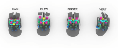
So which mouse grip style are you into?
The design has a fixed central core, with each button (including the central scroller) separately adjustable. The side panel with a pair of thumb buttons is also moveable. Creating a model in Rhino 3D working with the grasshopper visual programming environment [Charlies] explored the surface constraints for the base, claw, finger and vertical grip styles common among mouse users. This model was then fed into Fusion 360 for the detailed design. After completing the design, it was passed back into Rhino 3D to add lattice effects to the panel. This helps reduce weight and lets the internal LEDs shine through. The design is intended for resin printing, so you could go wild with the visuals by missing custom resins if you were so inclined.
It’s not news that Leonardo DaVinci was somewhat ahead of his time, and over the centuries many of the creations in his sketchbooks have been created and proved quite functional. The guys from the YouTube channel How To Make Everything have been looking at one such sketch, a screw thread-cutting machine. At first glance, it seems a little flawed. Threads are hard to make by hand, and you can see that this thread-cutting machine needs two identical threads operating as a reference to make it work. However, as the guys demonstrate, you can create threads by hand using simple methods.
Starting with an offset blade mounted on a block with a hole through it, a dowel can be scribed with a starter thread. This can then be worked by hand to cut enough of a groove for the application. They demonstrated that the machine was viable using nothing but wood for construction. A metal blade was mounted, and some preload force was applied to it with a spring. The dowel to be cut was loaded, and the machine ran back and forth enough times to create a very nice-looking screw thread. And once you’ve made two identical threaded dowels, you can use them to upgrade the machine or even build a second. Once you have a repeatable way to make such threads, all kinds of applications become more accessible. Need a bench vice? No problem now!
Whilst the demonstration doesn’t precisely follow the plans laid out by the master inventor, they aren’t all that clear on the cutting tool after all, it’s nice to see people still wanting to build his ideas, and we’ll certainly be following along.