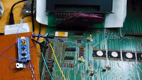
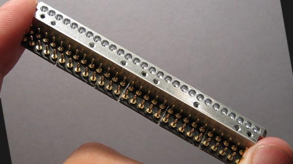
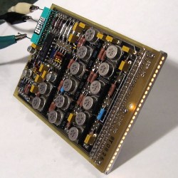
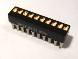
TRS-80 Gains Multiple Monitor Support, And High-Resolution Graphics

To call [Glen Kleinschmidt] a vintage computing enthusiast would be an understatement. Who else would add the ability to control and address multiple VGA monitors to a rack-mounted TRS-80 Model 1? Multiple 64-color 640×480 monitors might not be considered particularly amazing by today’s standards, but for 70s-era computing, it’s a different story.

Drawing this sin(x)/x ripple surface can be done in only 17 lines of BASIC.

How does a TRS-80 even manage to output anything useful to these monitors? [Glen] wrote his own low-level driver in machine code to handle that. The driver even has useful routines that are callable from within BASIC, meaning that programs written on the TRS-80 are granted powerful drawing abilities. Oh, and did we mention that the VGA graphics cards themselves were designed and made by [Glen]?

Interested in making your own? [Glen] provides all the resources you’ll need to re-create his work, including machine code drivers and demonstration BASIC programs as downloadable audio files, just as they would have been on original cassette tapes.

Watch things in action in the videos embedded below. The first draws a Land Rover, and the second plots a simple Moiré pattern star. Not bad for 70s-era hardware and 74xx logic!

Continue reading “TRS-80 Gains Multiple Monitor Support, And High-Resolution Graphics”

Custom Calculator Brings Us Back To The 70s

There are certain design aesthetics from every era that manage to survive the fads of their time and live throughout history. Ancient Greek architecture is still drawn upon for design inspiration in modern buildings, the mid-century modern style from the 60s still inspires various designs of consumer goods, and the rounded, clean looking cars from the 90s are still highly desirable qualities in automotive design. For electronics, though, we like this 70s-inspired calculator that [Aaron] recently built.

The calculator hearkens back to the days of calculators like the HP-29C with its large buttons and dot-matrix display. [Aaron] built the case out of various woods with a screen angled towards the user, and it uses a LCD display similar to those found in antique calculators. The brain of the calculator is an Arduino which fits easily into the case, and [Aaron] also built the keyboard from scratch with Cherry MX-style mechanical keys soldered together into a custom shape.

The software to run the calculator is fairly straightforward, but we are most impressed with the woodworking, styling, and keyboard design in this build. [Aaron] is also still ironing out some bugs with the power supply as it uses a DC-DC converter to power the device from a single lithium battery. For those who are more fond of early 2000s graphing calculators instead, be sure to take a look at this graphing calculator arcade cabinet.

Continue reading “Custom Calculator Brings Us Back To The 70s”

Vintage Calculator Design Shows Just How Much We Take For Granted Today

[Amen]’s Rockwell 920 calculator from the 70s was a very impressive piece of hardware for its time. It sported a 16-digit display, a printer, and it could run programs. It even had a magnetic card reader/writer that could be used to store programs and data externally. Seen through today’s eyes, it was less like a calculator and more like what we would call a single-board computer. They are also a window into another era, a time when many of the electrical design assumptions we take for granted hadn’t happened yet. When the time came to dig into what made the calculator tick, [Amen] had a lot of work to do just to get basic tools running.

For example, [amen]’s Blue Pill (an open-source, multipurpose test and measurement tool) is, on one hand, the perfect tool to snoop on the inner workings. However, those inner workings happen to use negative logic at -17 Volts, which means a logical zero is -17 V and a one is 0 V. Oh, and it uses an oddball clock rate, to boot. Since the Blue Pill doesn’t support -17 V negative logic (does anything?) a bit of custom work was needed to craft an interface. Once that was working, the Blue Pill was off to the races.

The unfamiliar elements didn’t end there. The pins on each IC, for example, are in a staggered layout quite unlike the DIP pattern most of us (and our tools, breadboards, and IC clips) are familiar with. As for the processor itself, [amen] has access to low-level documentation on Rockwell processors and instruction sets, but the timing diagrams are puzzling until one realizes the processor has two clock inputs at two different frequencies, resulting in what [amen] describes as four separate “clock phases”.

These design decisions were certainly made for good reasons at the time, and they even have a certain internal harmony to them, but it’s still a window into an era when the elements underpinning much of what we now have and work with had not yet happened.

Check out the video embedded below to see [amen] explain what it took to hook the Blue Pill up to a Rockwell 920. Also, if you’d like to see one of these vintage machines demonstrated in all its functioning glory, here’s a video of one being put through its paces.

Continue reading “Vintage Calculator Design Shows Just How Much We Take For Granted Today”

’75 Nixie Multimeter As Digital Dice

For the casual Monopoly or Risk player, using plain six-sided dice is probably fine. For other games you may need dice with much more than six sides, and if you really want to go overboard you can do what [John] did and build electronic dice with a random number generator if you really need to remove the pesky practice of rolling physical dice during your games of chance.

The “digital dice” he built are based on a multimeter from 1975 which has some hardware in it that was worth preserving, including a high quality set of nixie tubes. Nixies can be a little hard to come by these days, but are interesting pieces of hardware in their own right. [John] added some modern hardware to it as well, including an AVR microcontroller that handles the (pseudo) random number generation. A hardware switch tells the microcontroller how many sides the “die” to be emulated will need, and then a button generates the result of the roll.

This is a pretty great use for an old piece of hardware which would otherwise be obsolete by now. [John] considers this a “Resto-Mod” and the finish and quality of the build almost makes it look all original. It’s certainly a conversation piece at the D&D sessions he frequents.

A Daylight-Readable Bar Graph Display In The 70s Wasn’t Cheap

The driver board with display attached; the row of lamps is visible on the right hand side.

LEDs weren’t always an easy solution to displays and indicators. The fine folks at [Industrial Alchemy] shared pictures of a device that shows what kind of effort and cost went into making a high brightness bar graph display in the 70s, back when LEDs were both expensive and not particularly bright. There are no strange materials or methods involved in making the display daylight-readable, but it’s a peek at how solving problems we take for granted today sometimes took a lot of expense and effort.

The display is a row of 28 small incandescent bulbs, mounted in a PCB and housed in a machined aluminum frame. Holes through which to view the bulbs are on both the top and front of the metal housing, which allows the unit to be mounted in different orientations. It was made as a swappable module, its 56 machined gold pins mate to sockets on the driver board. The driver board itself consists of 14 LM119 dual comparators, each of which controls two bulbs on the display.

An example of a Wamco minitron bar graph display. Each window contains an incandescent filament. [Source: industrialalchemy.org]
[Industrial Alchemy] believes that the display unit itself may have been a bit of a hack in its own way. Based on the pin spacing and dimensions of the driver board, they feel that it was probably designed to host a row of modular units known as the Wamco minitron bar graph display. An example is pictured here; they resembled DIP chips and could be stacked side-by-side to make a display of any length. Each window contained an incandescent filament in a reflective well, and each light could be individually controlled.

These minitron bar graph units could only be viewed from the top, and were apparently high in cost and low in availability. Getting around these limitations may have been worth creating this compatible unit despite the work involved.

Display technology has taken many different turns over the years, and you can see examples of many of them in one place in the Circus Clock, which tells the time with a different technology for each digit: a nixie, a numitron, a 7-segment thyratron tube, a VFD, an LED dot display, and a rear projection display.

Soviet-Era 7-Segment Display, Built Like A Tank

In a way, all 7-segment displays are alike; at least from the outside looking in. On the inside it can be quite another story, and that’s certainly the case with the construction of this Soviet-era 7-segment numerical display. From the outside it may look a bit sturdier than usual, but it’s still instantly recognizable for what it is. On the inside is an unusual mixture of incandescent bulbs and plastic light guides.

The black-coated blocks of plastic on the left (shown from the rear) act as light guides. The holes are for nesting the incandescent bulbs. Note the puzzle-like arrangement of the uniquely shaped pieces.

The rear of the display is a PCB with a vaguely hexagonal pattern of low-voltage incandescent bulbs, and each bulb mates to one segment of the display. The display segments themselves are solid blocks of plastic, one for each bulb, and each a separate piece. These are painted black, with the only paint-free areas being a thin segment at the top for the display, and a hole in the back for the mating bulb.

The result is that each plastic piece acts as a light guide, ensuring that a lit bulb on the PCB results in one of the seven thin segments on the face being lit as well. An interesting thing is that the black paint is the only thing preventing unwanted light from showing out the front, or leaking from one segment to another; usually some kind of baffle is used for this purpose in displays from this era.

More curiously, each plastic segment is a unique shape apparently unrelated to its function. We think this was probably done to ensure foolproof assembly; it forms a puzzle that can only fit together one way. The result is a compact and remarkably sturdy unit that shows how older and rugged tech isn’t necessarily bulky. Another example of small display tech from the Soviet era is this tiny 7-segment display of a completely different manufacture, which was usually used with an integrated bubble lens to magnify the minuscule display.

Lo-Fi Greeting Card Sampler

We’re all familiar with record-your-own-message greeting cards. Generally they’re little more than a cute gimmick for a friend’s birthday, but [dögenigt] saw that these cards had more potential.

After sourcing a couple of cheap modules from eBay, the first order of business was to replace the watch batteries with a DC power supply. Following the art of circuit bending, he then set about probing contacts on the board. Looking to control the pitch of the recorded message, [dögenigt] found two pads that when touched, changed the speed of playback. Wiring these two points to the ears of a potentiometer allowed the pitch to be varied continously. Not yet satisfied, [dögenigt] wanted to enable looped playback, and found a pin that went low when the message was finished playing. Wiring this back to the play button allowed the recording to loop continuously.

[dögenigt] now has a neat little sampler on his hands for less than $10 in parts. To top it off, he housed it all in a sweet 70s intercom enclosure, using the Call button to activate recording, and even made it light sensitive with an LDR.

We’ve seen a few interesting circuit bends over the years – check out this digitally bent Roland TR-626 or this classic hacked Furby.

Check out the video under the break.

Continue reading “Lo-Fi Greeting Card Sampler”