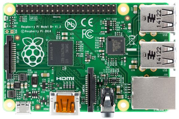
[Matthew’s] recent blog post does a good job explaining the basics of the Raspberry Pi’s file system. The Linux operating system installed on a Pi is generally installed on two different partitions on an SD card. The first partition is a small FAT partition. All of the files on this partition are used for the initial booting of the Pi. This partition also includes the kernel images. The second partition is the root file system and is generally formatted as ext4. This partition contains the rest of the operating system, user files, installed programs, etc.
With that in mind you can deduce that in order to backup your Pi, all you really need to do is backup all of these files. [Matt] has written some scripts to make this a piece of cake (or pie). The first script will simply copy all of the files into a gzipped archive. You can save this to an external SD card, USB drive, or network share.
The second script is perhaps more interesting. This script requires that you have one free USB port and a USB SD card reader. The script will automatically format the extra SD card to contain the two critical partitions. It will then copy the “boot” files to the new boot partition and the root file system files to the new SD card’s root partition. When all is said and done, you will end up with an SD card that is an exact copy of your current running file system.
This can be very handy if you have multiple Pi’s that you want to run the same software, such as in a Pi cluster. Another good example is if you have spent a lot of time tweaking your Pi installation and you want to make a copy for a friend. Of course there are many ways to skin this cat, but it’s always fun to see something custom-built by a creative hacker.


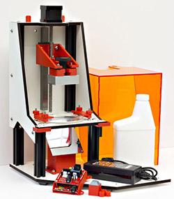 Over the last few years, a few resin / stereolithography printers have been made a few headlines due to print quality that cannot be matched by the usual RepRap style filament printers. These used to be extremely expensive machines, but lately there have been a few newcomers to the field.