Ocelot Arcade System Illustrates The Scope Of Vector Graphics

Who knows how far the Vectrex system, or vector graphics gaming in general could have gone if not for the crash of ’83? The console wars might have been completely different if not for this market saturation-based reset button.

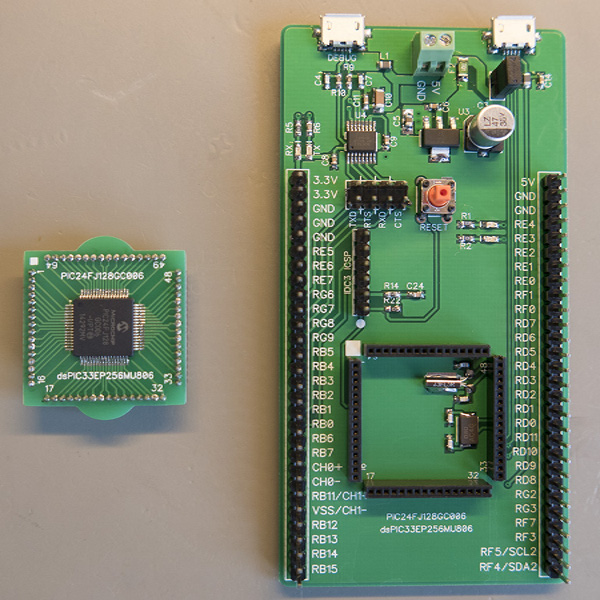
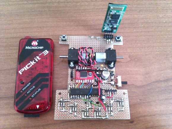
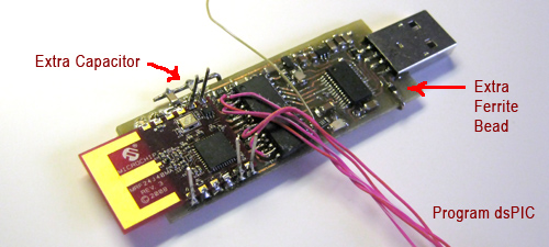
[Matt Carr] doesn’t own a Vectrex, but he does have a Tektronix 465 oscilloscope. After an intense labor of love and documentation, he also has a shiny new vector graphics arcade system that he built himself. It’s based on a dsPIC33 and uses a dual-channel DAC to produce wire frame 3-D graphics and send X-Y coordinates to the ‘scope via phono outputs. The PIC’s internal DAC is meant for audio and didn’t do so well with graphics, so [Matt] used a TLV5618A piggybacked on the PIC’s DAC pins.

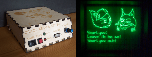
The Ocelot doesn’t take cartridges, though it might someday. For now, changing games means getting out the PICkit. There are currently two to choose from: Star Lynx, an awesome flying shooter where you get to save a feline population, and Mattsteroids, which is exactly what it sounds like. There’s only one Ocelot in existence, and although it isn’t for sale, [Matt] has terrific technical documentation should you care to replicate it. One thing you might not be able to replicate is the awesome vintage advert he made for the Ocelot, which is cued up after the break.

Don’t have a ‘scope? You can do vector graphics on a CRT with an FPGA.

Continue reading “Ocelot Arcade System Illustrates The Scope Of Vector Graphics”

Get Your Kicks With This New PIC Development Board

While development boards for micro controllers are nothing ground breaking, they can be expensive, and often times overkill for what you’re doing when they try to put everything you might use … including the kitchen sink. when [Brian] noticed his projects were starting to use Microchip PIC24 more and more, the time came to have a dev board on hand. 

top-viewThe result is a small board with breakouts for USB, UART (via FTDI), of course tons of GPIO pins, and a socket which mates with a daughter board to swap out either a PIC24FJ128GC006, or a DSPIC33EP256MU806, with the potential for more. Also packed on the board is a power regulator system and dual crystals allowing full speed operation or power sipping modes.

Schematics and PCB layout are available (in Diptrace format) along with a board template file to use with MPLAB on github.com. Once you have everything together you will need a PIC programmer, [Brian] is using a trusty Microchip MPLAB ICD 3 programmer, but naturally, others are available.

Microchip recently announced a new development board of their own for the PIC16F series. The Curiosity board has built-in support for programming and debugging (no chipKIT needed). The engineer who designed that board, [John Mouton] is going to join us on July 30th for a live chat about the design process. We’re also going to be giving away some of the first boards to come off the production line… more about that this coming week.

Protoboard Line Following Robot

dspic-line-follower

We love a good line-following robot project and this really hits the spot. It’s got sharp edges, gobs of solder bridging, and look at all those jumper wires! Despite its appearance it puts in a performance that won’t disappoint.

It uses a dsPIC33 to read from half a dozen analog sensors on the bottom of the board. We’re not all that familiar with the chip’s features, but [Exapod] says it’s got an auto-scan feature he uses to read the sensors. This allows him to sample with 12-bit resolution from all six of them at about 30 kHz. No wonder the thing is so responsive in the demo video embedded below. The track he’s using is just some white printer paper with a fat circuit of black electrical tape placed in a somewhat squiggly pattern.

This is also a fun challenge with toys. Here’s one that hacks a hexapod to follow the lines.

Continue reading “Protoboard Line Following Robot”

Wireless Base Station Eavesdrops On Robot Communications

wireless-base-station-evesdrops-on-robot-communications

The good [Doctor Iguana] has been working on a pair of robots which communicate with each other using mRF24J40MA wireless transceivers. This presents a challenge in debugging, as he really didn’t have an easy way of monitoring those communications. His solution was to build his own base station which lets him use a computer to monitor what each robot is saying.

He spun his own board for the project. USB connectivity is provided by an FTDI chip, the FT232RL. This converts the USB communications in to serial for the dsPIC33 microcontroller. The FTDI chip comes with a fairly fine-pitch, but the footprint can still be fabricated using toner transfer if you’re fairly familiar with the process. [Dr. Iguana] took some close-up images of the unpopulated board which might make you a little nervous with the soldering iron. The other end of the board hosts the same Microchip wireless module as he used in his robots.

After a bit of rework (noted on the photo labels) he got this up and running. Now he can capture all of the wireless communications and see if problems are due to the sender or the receiver.

High Speed Stepper Driving: 25k Steps Per Second

Stepper motors are pretty easy to control with a microcontroller. But if you’re looking to run then at a high number of revolutions per second things get tricky pretty quickly. [Uwe’s] been learning about and building stepper drivers for years, and recently he decided to build a high-performance driver based on a MicroChip reference design.

As with the reference design, his board uses a dsPIC33. But instead of using a series of discrete MOSFETS to switch the signals to the motor, he sourced an L298N motor driver. That’s it sticking up next to the large capacitor. When driven hard it needs its own heat sink, which [Uwe] cut from a larger CPU heat sink. During development, he decided to use interrupt-based PWM rather than the hardware PWM offered by the dsPIC. It works, but he would go the other route if doing it again.

For the pedestrian, the video after the break has all the details you need. For those that really want to dive in, [Uwe’s] multi-paged write-up is worth bookmarking.

Continue reading “High Speed Stepper Driving: 25k Steps Per Second”

Autonomous Rover Roams The Halls

[ESylin] built an autonomous rover that roams the vacant halls of his school. On the hood of the vehicle he’s mounted two Maxbotix sonar sensors that do a great job of keeping the vehicle centered in the hallway. It will follow a wall around a corner (favoring its left side because of the left-facing sensor) and it will stop to correct itself if it gets off course. That’s because when you’re not driving a dsPIC33 is, with a Traxxas XL-5 speed controller and a hobby servo for steering. But this little guy hasn’t lost all his pep. Manual control and be switched on from from an R/C controller so you can burn up the floor tiles. Take a look at the demo after the break, with the manual control demo shown at about 4:10. Continue reading “Autonomous Rover Roams The Halls”