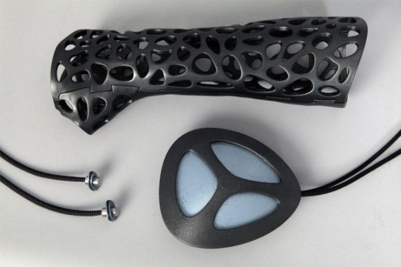
A Better USI I2C Library For The MSP430

USI

TI’s MSP430 chips are rather interesting – they’re low power, very capable, and available for under a dollar in most cases. Some of these chips, though, don’t have native SPI or I2C interfaces; instead, everything is done through a USI, or Universal Serial Interface module. [Jan] found the stock I2C USI module was a little rough around the edges, so he created his own.

[Jan] found the TI example code for using the USI as an I2C device overly complicated and something that an intern whipped up in a week and was never touched again. In response to this, he created a much, much simpler USI/I2C module that’s actually readable. It’s available over on the GitHub if you want to grab it for yourself.

Compared to the TI code, [Jan]’s library is dead simple. There are only two functions, one for initialization, and another for sending and receiving. Easy, small, and it works. Can’t do much better than that.

This Space Saver Puts The Squeeze On Your Keys

MultiKey

Keys? Who needs them? Well, pretty much everyone. You can’t deny that there are some ridiculously crowded key chains out there. It’s clear that [Robb] wanted to hit the other side of that spectrum when he started working on his latest multi-key project.

The term “multi-key” may be a little misleading as there are more than just keys on this tool. In addition to the bike lock, locker, work and house keys, there is a USB drive, bottle opener, screw driver and a couple of Allen wrenches. The side frames started out as part of an Allen key combo set; one not of the highest quality.  The Allen keys started snapping off during use which left [Robb] with a set of otherwise useless side frames. These became the platform of which [Robb’s] project is based. Adding a couple new bolts, nuts and a few modified keys got him the rest of the way there. A lot of thought went into which items to put into this tool and [Robb] explains his thought process in his step-by-step instructions.

The simple nature and potential for customizing makes this a great utilitarian DIY project. Although this may not be Janitor worthy, it will certainly consolidate some of the bulk in our pockets.

The Most Horrifying Use Of 3D Printing

As anyone with a Facebook account that’s over the age of 25 will tell you, 3D ultrasounds of fetuses are all the rage these days, with ultrasound pictures of the unborn recently taking the leap from black and white blobs to 3D – and 4D – images. With the advent of 3D printers, the inevitable has happened. Now you can order a 3D print of your yet-to-be-born progeny.

The company behind this – 3D Babies – takes 3D ultrasound data from weeks 24-32 and turns it into a 3D model. The printed 3D models sell for $800 for the full size version, $400 for a half-size version, and $200 for a quarter size version. It appears the 3D ultrasound data is simply wrapped around a pre-defined mesh, so while the resulting print may come out looking like your spawn, it’s still not a physical copy of the 3D/4D ultrasound data.

Despite the ‘creepy’ factor of these little bundles of plastic, we’re wondering why we haven’t seen anything like this before. Are there any obstetricians/radiologists/ultrasound techs out there that have experience with importing 3D ultrasound data into an editor of some sort? Notwithstanding any HIPAA violations, it seems it would be rather easy to turn this sort of 3D data into a printed object. 3D printing CT scans models can’t be the only other instance of this type of thing.

Thanks [Will] for the nightmares

Rewriting WS2812 Driver Libraries For Optimization

ws2812_compared

We like [Tim’s] drive for improvement. He wrote a WS2812 driver library that works with AVR and ARM Cortex-M0 microcontrollers, but he wasn’t satisfied with how much of the controller’s resources the library used to simply output the required timing signal for these LED modules. When he set out to build version 2.0, he dug much deeper than just optimizing his own code.

We remember [Tim] from his project reverse engineering a candle flicker LED. This time, he’s done more reverse engineering by comparing the actual timing performance of the WS2812(B) module with its published specs. He learned that although several timing aspects require precision, others can be fudged a little bit. To figure out which ones, [Tim] used an ATtiny85 as a signal-generator and monitored performance results with a Saleae logic analyzer. Of course, to even talk about these advances you need to know something about the timing scheme, so [Tim] provides a quick run-through of the protocol as part of his write-up.

Click the top link to read his findings and how he used them to write the new library, which is stored in his GitHub repository.

Oscilloscope Repair Projects Still Probing For Success

lecroy-9450-oscilloscope-repair[Luke] isn’t able to declare total victory yet. His LeCroy 9450 oscilloscope repair project has seen some success, though. The glitchy screen seen above is just one of the problems it had, but has now been fixed. When [Luke] got his hands on it, this was one of three screen states: the other two being normal operation or completely dead. Replacing the screen connector was all it took, so he moved on to the second part.

This one is much less trivial. Only one of the two channels works—which might be the point at which many would abandon the repair—but it’s still a fine single-channel scope. [Luke] continued to trouble-shoot by disassembling the bottom of the case and breaking out the device’s schematics. He traced the circuit and found one module that is suspect (and is looking for help finding a replacement). Unfortunately, the problems don’t end there. Another unknown problem is causing erroneous signals on the displayed waveforms. It’s an odd issue but it really feels like he’s close to solving this one!

RasPi “Inception” CD-ROM Case Mod

raspiInception

At first glance, [John’s] CD-ROM RasPi case may not seem all that unique, but we like both the implementation as well as the end-result functionality it provides. His goal was to use the Pi as a torrent downloader, and to store the downloaded files on a shared network drive. The Pi drive would slide into a bay in the server’s case—hence the Inception reference: a computer in a computer—allowing downloads while putting another step between the server and the outside world keeping, as well as guaranteeing that the network share would be available, because the server and the Pi would use the same power source.

[John] gutted the CD-ROM’s internals to leave only the PCB, which he stripped of most everything save for the power connector in the back. He then used the base of his old RasPi case as a standoff, mounting it to the top of the CD-ROM’s PCB. He soldered the power lines to the ROM’s power connector and temporarily hooked up a 5V adapter until he gets the server running. The final step was to carve out the back of the case for access to the Ethernet and USB ports, which [John] accomplished with a dremel, a hacksaw and a file. The front of the case still looks like a stock CD-ROM drive, and [John] has plans for future mods: re-purposing the LED to show network activity and modifying the buttons to serve as a reset, pause, or start for torrent downloads.

Controlling Alphanumeric LCDs With Two Wires

LCD

The Hitachi HD44780 LCD controller is the most common interface to all those alphanumeric LCDs out there, and there are a million and one tutorials for connecting these displays to any microcontroller imaginable. This still doesn’t mean hooking up these displays is necessarily simple, though: you still need at least four wires for the data, at least two for control signals, and power and ground lines for connecting the LCD the traditional way.

Here’s a neat trick for connecting HD44780 displays that only needs two wires. In this setup there’s only a ground and power+data wire. The interesting part of this build is using the power pin to transmit serial data with an RS-232-like format. The only difference is keeping the data line at +5 V when idle; a reasonable-sized cap keeps the display and controller alive when the master microcontroller is transmitting.

This technique does require a bit of logic on the receiving end, which a small 8-pin PIC can handle with ease. Communication between a microcontroller and this “smart” LCD is done at 2400 bps, which even the wimpiest micro can handle. All the software to make this setup work are available here, and we expect an Atmel-based version to hit the Hackaday tip line shortly.