Every electronics project of sufficient complexity needs standoffs – little plastic or metal cylinders – to mount boards to one another. Keeping hundreds of little plastic trinkets around doesn’t really fit with the hacker mentality, though: it would be far simpler to keep some Delrin rod stock around to drill and cut standoffs as needed. [HomeCSP] created a device to do just that, allowing him to turn 1/4″ Delrin rod stock into any size standoff he needs.
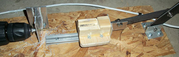
Before building this device, [HomeCSP] was taking plastic rods to the drill press fitted with a very tiny drill bit for a #2 screw. The problems with that technique should be evident to anyone. The new solution uses an old cordless drill and a 6 inch piece of linear rail, effectively turning some bits of scrap into a horizontal drill press with a stationary bit.
The end result is a machine that can bore a hole straight down a 1/4″ rod. With a box of screws these homebrew plastic rods are much cheaper than off-the-shelf parts and can be made in any length desired.