“The lathe is the only machine tool that can make copies of itself,” or so the saying goes. The reality is more like, “A skilled machinist can use a lathe to make many of the parts needed to assemble another lathe,” which is still saying quite a lot by is pretty far off the implication that lathes are self-replicating machines. But what about a 3D printer? Could a printer print a copy of itself?
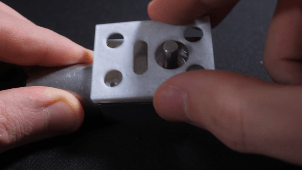
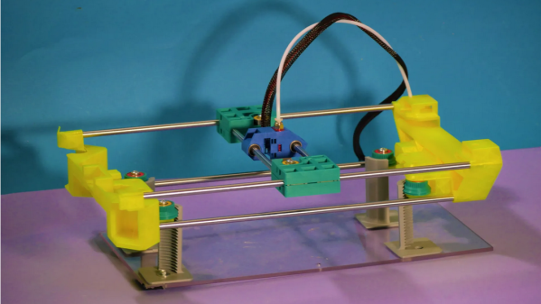
Not really, but the Infini-Z 3D printer certainly has some interesting features that us further down the road to self-replication. As the name implies, [SunShine]’s new printer is an infinite Z-axis design that essentially extrudes its own legs, progressively jacking its X- and Y-axis gantry upward. Each leg is a quarter of an internally threaded tube that engages with pinion gears to raise and lower the gantry. When it comes time to grow the legs, the print head moves into each corner of the gantry and extrudes a new section onto the top of each existing leg. The threaded leg is ready to use in minutes to raise the gantry to the next print level.
The ultimate goal of this design is to create a printer that can increase its print volume enough to print a copy of itself. At this moment it obviously can’t print a practical printer — metal parts like bearings and shafts are still needed, not to mention things like stepper motors and electronics. But [SunShine] seems to think he’ll be able to solve those problems now that the basic print volume problem has been addressed. Indeed, we’ve seen complex print-in-place designs, assembly-free compliant mechanisms, and even 3D-printed metal parts from [SunShine] before, so he seems well-positioned to move this project forward. We’re eager to see where this goes. Continue reading “Infinite Z-Axis Printer Aims To Print Itself Someday”