Race Car POV LED Displays

race_car_pov

Last year, when [Alex] was asked by his friend [Martin] to help him out with building some LED POV modules for a race car, his response was a enthusiastic “YES!”

[Martin’s] goal was to involve fans more deeply in the race, so he decided that the POV modules would carry messages from fans on-board, printing them in the night as the race cars screamed around the track. The pair started prototyping and testing a design, wrapping things up shortly before this year’s 24 hours of Nürburgring.

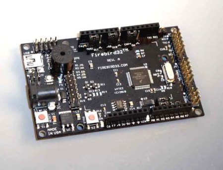
The modules consist of an Arduino-compatible AVR, a GPS module, a 16-LED light bar, and the circuitry for driving the LEDs. While most of the components are pretty standard fare, the we don’t often see a GPS sensor built into a POV display. [Alex] says that the sensor is used to calculate the speed of the cars, ensuring a uniform font size.

They took their LED displays to the 24 hours of Nürburgring, where they were invited by Audi to install the modules on a pair of R8 Le Mans race cars. As you can see by the pictures on his blog and Flickr set, the POV units worked out nicely without having to stretch the camera exposure times too far.

If you’ re interested to hear a bit more about how the displays were built, check out this entry in[Alex’s] blog, where he goes through some additional details.

Update:[Alex] pointed us to the videos!

Arduino Video Sampler

[gijs] sent in an Arduino video sampler he’s been working on. The sampler is able to capture, pause and play a short video forwards and backwards.

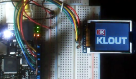
The video capture circuit is based on the Nootropic Design video experimenter. We’ve seen a few project use this video experimenter board, but never with such smooth video. The sampler samples frames at a resolution of 128×96 and stores everything in a 256Kbit SRAM. A back-of-the-envelope calculation tells us that the sampler can hold a little under a second of video, more than enough to do something cool.

[gijs] says there is a 1 bit version and a 1.5 bit version of his video sampler. While we’re busy wrapping our minds around what half a bit is, he’ll be upgrading the 1.5 bit version to 2 bits. He’s also ordered some PCBs and expects to have a kit out by October. Check out a demo after the break.

Continue reading “Arduino Video Sampler”

Building A Single-button Combination Lock

single_button_arduino_combination_lock

[John Boxall] of Little Bird Electronics was thinking about combination locks, and how one might improve or at least change the way these locks work. Traditional combo locks can be implemented in a variety of ways, most of which we are all familiar with. Standard rotary padlock and keypad-based electronic safes work just fine, but he was interested to see how one might implement a single button combination lock.

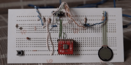
[John] determined that the best, if not only way, to build this sort of lock would require him to measure button press intervals. In his case he decided to monitor the intervals between his button presses instead, but the concept is the same. He first tested himself to see how accurately he could press and release the button, leaving a one-second space between presses. After looking at the results he determined that he would need to incorporate at least a 10% margin for error into his code in order to compensate for human error.

He then created an Arduino sketch to test his idea, defining a set of key press intervals that could be used to ‘unlock’ his imaginary vault. It worked quite well, as you can see in the video demo below.

Now we’re not suggesting that you lock up your mint condition My Little Pony collection or your illegal arms stash with this type of lock, but it could be useful as an extra failsafe for certain projects/gadgets that you want to keep all to yourself.

Continue reading “Building A Single-button Combination Lock”

A Beginner’s Guide To Magnetometers

magnetometers_for_beginners

The folks over at LoveElectronics recently published an article that explains some of the ins and outs of magnetometers for those who are interested in trying one out, but might not understand how to use them.

A good part of the article focuses specifically on how to manipulate the HMC5883L magnetometer from Honeywell, but a lot of the information can be applied to other makes/brands of compass sensors. They start out discussing in very basic terms how the compass works, then delve into some specifics on how to interface the chip with an Arduino, courtesy of a breakout board that they sell. The breakout board is actually quite simple, so any number of custom iterations could be built for your own testing purposes.

They walk through the use of an HMC5883L-specific Arduino sketch they produced, making it easy for beginners to start getting useful data from the compass units. While a pre-made sketch might seem like a bit of a cop out, it at least gives the curious/motivated beginner a chance to look at some completed code in order to see how things work.

If you are interested in cutting your teeth on some additional beginner concepts, check out these other how-to articles and tutorials.

Controlling A Counter Top Water Distiller With Salvaged Parts

distiller_power_off_timer

Hackaday reader [Kyle] wrote in to share a project he recently wrapped up, involving a counter top water distillation unit he uses at home.

He lives in Atlanta, and hates both the taste and contaminants in the water, so using this distiller is an absolute must in his house. The problem with this cheap unit is that it waits until it is completely dry before shutting off the heating element. According to [Kyle] this brings up two huge problems.

First, letting the unit run dry simply vaporizes all of the contaminants that he was trying to remove, allowing them to re-condense and contaminate his fresh water. Second, the heating element reaches extreme temperatures once the water is gone, which causes premature failure of the distillation unit.

He originally used a timer to remind himself to turn off the unit before it ran dry, but the process became tedious. He found that he would often forget to turn off the distiller before it ruined his newly cleaned water.

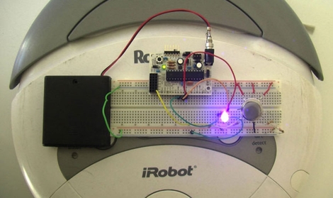
Looking for another solution, he decided to automate the process using some components left over from an Arduino-based terrarium temperature/humidity controller he built a while back. A salvaged toy clock tower was used as an input dial, which sets the distillation time on the microcontroller. The Arduino in turn manages a set of relays that controls the power supply to the distiller.

While [Kyle] only sent us this information to us via email, he has made code and pictures available online. We’re sure he would be pretty open to answering any questions you might have related to his build, so fire away in the comments section.

[Update]
After seeing that his distiller made the front page, [Kyle] directed us to a write up he prepared, detailing some more specifics on the project.

Bubble Blowing Bot Blows Big Bouncy Bubbles


[Rob] Was cleaning out his car hole when he stumbled across a servo, a PC cooling fan, an Arduino and apparently a whole lot of bubble mixture. With all of this, some scrap timber and a few trips to the dollar store, he was able to whip up this bubble blowing bot to entertain his children. It looks like a fairly simple mechanism, the servo tips the old pipe bend into the sudds and the fan provides the air to blow the bubble. The size of the bubble is varied by altering the speed that the pipe bend tips.

The video after the break shows the robot blowing some nice big bubbles, and a quick view of the fan and servo mechanism. There is not a lot of information available but we find the motion of the pipe bend and the big bubbles it blows entertaining, you know the saying, “simple things…”

Continue reading “Bubble Blowing Bot Blows Big Bouncy Bubbles”

ChibiMo – An AVR-based USB Display

chibimo_usb_arduino_external_monitor

[Ko] wanted to add an extra monitor to his computer, but he wasn’t looking for something huge that would sit atop his desk – he desired something smaller, much smaller.

His ChibiMo mini USB monitor is a neat little creation that lets you extend or mirror your Windows desktop onto a tiny 128×64 pixel LCD panel. At first glance you might think that it is too small to be useful, but it is recognized in Windows in the same fashion as any standard monitor. This means that it would be quite easy to load system monitoring software solely on the LCD panel, keeping the clutter off of your main display.

The display is wired to an Arduino like any other standard shield, and is connected to his computer via a USB cable. Once the ChibiMo sketch is uploaded to the Arduino, the display driver needs to be loaded on the PC. This allows you to tweak the ChibiMo’s display settings in Windows’ display manager.

It’s a great concept, one we would love to see explored further. As of right now, the ChibiMo is only supported on x86 versions of Windows XP, and we weren’t able to find source links anywhere on his site. Perhaps there are some talented members of our community who would be interested in taking a whack at it…