A Motherboard Manufacturer’s Take On A Raspberry Pi Competitor

In the almost five years since the launch of the original Raspberry Pi we have seen a huge array of competitors emerge in the inexpensive single board computer market. Many have created their own form factors, but an increasing number have gone straight for the jugular of the fruity board from Cambridge by copying its form factor and interfaces as closely as possible. We’ve seen sterling efforts from the likes of Banana Pi, Odroid, and several others, but none have yet succeeded in toppling it from its pedestal.

The ASUS Tinker specification.

The latest contender in this arena might just make more of an impact though, because it comes from a major manufacturer, a name you will have heard of. Asus have quietly released their Tinker, board that follows the Pi form factor very closely, and packs a 1.8 GHz quad-core ARM Cortex A17 alongside an impressive spec we’ve captured as an image for this article. Though they are reticent about it on their website, there is a SlideShare presentation with some of the details, which we’ve placed below the break.

At £55 (about $68) where this is being written it’s more expensive than the Pi, but Asus go to great lengths to demonstrate that it is significantly faster. We will no doubt verify the accuracy of that claim as the boards find their way into the hands of our community. Still, it features a mostly-Pi-compatible I/O header, and the same display and camera connectors as the Pi. There is no information as to how compatible these last two are though.

Other boards in this arena have boasted impressive hardware, but have fallen down when it comes to the support for their operating systems. When you buy a Raspberry Pi it is not just the hardware you are taking on but the Raspbian operating system and its impressive community support. The Tinker supports Debian, so if Asus is to make a mark they must ensure that its support rivals that of the board it is targeting. If they succeed in that endeavor then the result can only be good news for us.

Continue reading “A Motherboard Manufacturer’s Take On A Raspberry Pi Competitor”

The Cardboard Computer

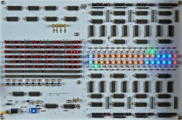
Every time we say “We’ve seen it all”, along comes a project that knocks us off. 60 year old [Mark Nesselhaus] likes to learn new things and he’s never worked with hardware at the gate level. So he’s building himself a 4-bit Computer, using only Diode-Transistor Logic. He’s assembling the whole thing on “card board” perf-board, with brass tacks for pads. Why — because he’s a thrifty guy who wants to use what he has lying around. Obviously, he’s got an endless supply of cardboard, tacks and Patience. The story sounds familiar. It started out as a simple 4-bit full adder project and then things got out of hand. You know he’s old school when he calls his multimeter an “analog VOM”!

It’s still work in progress, but he’s made a lot of it in the past year. [Mark] started off by emulating the 4-bit full adder featured on Simon Inns’ Waiting for Friday blog. This is the ALU around which the rest of his project is built. With the ALU done, he decided to keep going and next built a 4-to-16 line decoder — check out the thumbnail image to see the rats nest of jumbled wires. Next on his list were several flip flops — R-S, J-K and D types, which would be useful as program counters. This is when he bumped into problems with signal levels, timing and triggering. He decided to allow himself the luxury of adding one IC to his build — a 555 based clock generator. But he still needed some pulse shaping circuitry to make it work consistently.

from right, Input, +5V, nc, gnd
LED Driver : from left, Gnd, NC, +5V, Input

[Mark] also built a finite-state-machine sequencer based on the work done by Rory Mangles TinyTim project. He finished building some multiplexers and demultiplexers, and it appears he may be using a whole bank of 14 wall switches for address, input and control functions. For the output display, he assembled a panel using LED’s recovered from a $1 Christmas light string. Something seems amiss with his LED driver, though — 2mA with LED on and >2.5mA with LED off. The LED appears to be connected across the collector and emitter of the PNP transistor. Chime in with your comments.

This build seems to be shaping along the lines of the Megaprocessor that we’ve swooned over a couple of times in the past. Keep at it, [Mark]!

Continue reading “The Cardboard Computer”

An Intel 8085 Microprocessor Trainer

The Intel 8085 microprocessor was introduced 40 years back, and along with its contemporaries — the Z80 and the 6502 — is pretty much a dinosaur in terms of microprocessor history. But that doesn’t stop it from still being included in the syllabus for computer engineering students in many parts of the world. The reason why a 40 year old microprocessor is still covered in computer architecture text books instead of computer history is a bit convoluted. But there’s a whole industry that thrives on the requirements of college laboratories and students requiring “8085 Microprocessor Training Kits”. [TisteAndii] just finished college in Nigeria, where these kits are not locally built and need to be imported, usually costing well over a 100 dollars.

Which is why his final year project was a low cost Intel 8085 Microprocessor Trainer. It’s a minimalist design with some basic read/write memory, program execution and register inspection, with no provision for single stepping or interrupts yet. The monitor program isn’t loaded in an EEPROM. Instead, a PIC18 is used and connected to the 8085 address, data and control pins. This makes it easier to write a monitor program in C instead of assembly. And allows use of a 1.8″ LCD with SPI interface instead of the more usual 7-segment displays used for these kind of kits. [TisteAndii] built a 6×4 keyboard for input, but couldn’t solve debounce issues and finally settled on a 5×4 membrane keypad.

Being a rookie, he ended up with a major flaw in his board layout — he missed connecting the SRAM and the PPI devices to the data bus. A bunch of jumper links seemed to solve the issue, but it wasn’t perfect. This, and a few other problems gave him a lot of grief, but towards the end, it all worked, almost. Most importantly, his BoM cost of about $35 makes it significantly cheaper compared to the commercial units available in Nigeria.

While some hackers may consider this a trivial project, it solves a local problem and we hope the next iteration of the design improves the kit and makes it more accessible.

C64 Keyboard Emulation Over Serial

There’s a lot of reasons you might want to emulate the keyboard on your Commodore 64. The ravages of time and dust may have put the original keyboard out of order, or perhaps you need to type in a long program and don’t fancy pecking away with the less-than-stellar feedback of the standard keys. [podstawek] has come up with the solution: a Commodore 64 keyboard emulator that works over serial.

It’s a simple concept, but one that works well. A Python script accepts incoming keypresses or pre-typed text, then converts them into a 6-bit binary code, which is sent to an Arduino over the serial connection. The Arduino uses the 6-bit code as addresses for an MT8808 crosspoint switch.

MT8808 Functional Diagram from Datasheet

The MT8808 is essentially an 8×8 matrix of controllable switches, which acts as the perfect tool to interface with the C64’s 8×8 keyboard matrix. Hardware wise, this behaves as if someone were actually pressing the keys on the real keyboard. It’s just replacing the original key switches with an electronic version controlled by the Arduino.

[podstawek] already has the setup working on Mac, and it should work on Linux and Windows too. There’s a little more to do yet – modifying the script to allow complex macros and to enable keys to be held – so check out the Github if you want to poke around in the source. Overall it’s a tidy, useful hack to replace the stock keyboard.

The C64 remains a popular platform for hacking — it’s even had a Twitter client since 2009.

FPGA Computer Covers A To Z

[F4HDK] calls his new computer A2Z because he built everything from scratch (literally, from A to Z). Well, strictly speaking, he did start with an FPGA, but you have to have some foundation. The core CPU is a 16-bit RISC processor with a 24-bit address bus and a 128-word cache. The computer sports 2 megabytes of RAM, a boot ROM, a VGA port and keyboard, and some other useful I/O. The CPU development uses Verilog.

Software-wise, the computer has a simple operating system, a filesystem, and basic programs like a text editor and an image viewer. Development software includes an assembler and a compiler for a BASIC-like language that resides on the PC. You can also run an emulator to experiment with A2Z without hardware. You can see a “car game” running on A2Z in the video below. You can also see videos of some other applications.

Continue reading “FPGA Computer Covers A To Z”

Semi-automatic Mouse Requires No Permit

When [Kerry]’s son asked him if there was a way to make a mouse click rapidly, he knew he could take the easy way and just do it in software. But what’s the fun in that? In a sense, it’s just as easy to do it with hardware—all you have to do is find a way to change the voltage in order to simulate mouse clicks.

[Kerry] decided to use the venerable 555 timer as an astable oscillator. He wired a momentary button in parallel with the left mouse button. A 50k mini pot used as the discharge resistor allows him to dial in the sensitivity. [Kerry] found that he maxed out around 5 clicks per second when clicking the regular button, and ~20 clicks per second with the momentary button as measured here. The mouse still works normally, and now [Kerry]’s son can totally pwn n00bs without getting a repetitive stress injury. M1 your way past the break to check out [Kerry]’s build video.

There are lots of other cool things you can do with an optical mouse, like visual odometry for cars and robots.

Continue reading “Semi-automatic Mouse Requires No Permit”

The Tiny SCSI Emulator

For fans of vintage computers of the 80s and 90s, SCSI can be a real thorn in the side. The stock of functioning hard drives is dwindling, and mysterious termination issues are sure to have you cursing the SCSI voodoo before long. Over the years, this has led to various projects that aim to create new SCSI hardware to fill in where the original equipment is too broken to use, or too rare to find.

[David Kuder]’s tiny SCSI emulator is designed for just this purpose. [David] has combined a Teensy 3.5 with a NCR5380 SCSI interface chip to build his device. With a 120MHz clock and 192K of RAM, the Teensy provides plenty of horsepower to keep up with the SCSI signals, and its DMA features don’t hurt either.

Now, many earlier SCSI emulation or conversion projects have purely focused on storage – such as the SCSI2SD, which emulates a SCSI hard drive using a microSD card for storage. [David]’s pulled that off, maxing out the NCR5380’s throughput with plenty to spare on the SD card end of things. Future work looks to gain more speed through a SCSI controller upgrade.

But that’s not all SCSI’s good for. Back in the wild times that were the 80s, many computers, and particularly the early Macintosh line, were short on expansion options. This led to the development of SCSI Ethernet adapters, which [David] is also trying to emulate by adding a W5100 Ethernet shield to his project. So far the Cabletron EA412 driver [David] is using is causing the Macintosh SE test system to crash after initial setup, but debugging continues.

It’s always great to see projects that aim to keep vintage hardware alive — like this mass repair of six Commodore 64s.