After getting his hands on a rope driver module from the Apollo project era that had a big ‘Scrapped Module’ stamped on it, [Mike Stewart] was naturally left curious as to what exactly had failed in this module. Originally destined for the Apollo Guidance Computer, these Raytheon-manufactured modules were the pinnacle of space-grade high-tech of the 1960s, with requisite acceptance testing so as to not endanger a very expensive space mission.
The cool part here is that the acceptance documents for the module in question (B16-B17) have been scanned in and can be found on the Internet Archive. With the part itself being potted and very much inaccessible, this document helpfully lays out the expected measurements on the module’s pins, as well as schematics and mechanical drawings. Unfortunately the reasons for the rejection were not recorded, so replicating the failing test results is required to understand the reason.
A slight complication here is that the testing procedure doesn’t just involve hooking up a multimeter for some voltage and capacitance measurements. There are also temperature and voltage extremes, and vibration tolerance involved, which would be somewhat complex to test, but most of all risk damaging a historical artefact. Thus a somewhat conservative testing procedure was chosen, even if this may not reveal the actual fault.
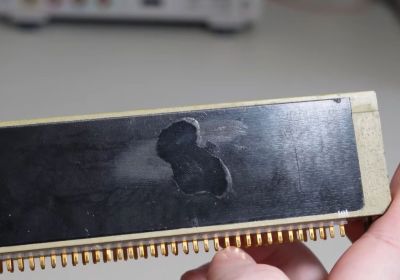
As noted in the video, sometimes modules were also rejected because someone simply dropped it on the floor along the way. However, generally if a module was found to be faulty they would open it to diagnose said fault, with a closer look at this module indeed revealing suspicious marks in the potting compound where it was apparently opened and conceivably repaired. This also might explain why they also put the ‘For engineering use only’ on it.
With multiple of such locations visible in the potting compound, these locations were mapped to the schematics for the module, to get some idea of what may have been accessed. After this, basic testing was performed on the module, as per the acceptance testing document.
Along the way an error was detected in said document, in the form of the wrong pin number. In table 4-2 the input pin 269 was mistakenly listed as having output pin number 169 when it should have been pin 168. Pin 169 is chassis ground, so this was presumably fixed in a later version of the document.
After all the testing with just stationary, room-temperature conditions, everything appeared to check out. This means that likely this was indeed a repaired module that got subsequently used for engineering purposes rather than installed in flight-ready hardware. The only issue found was that channels were out of calibration, but whether this was an original flaw or due to the module being half a century old is hard to tell in the absence of repair logs.
Overall it’s an exciting opportunity to document another part of history, since so many of the details pertaining to these original modules and related technologies got lost or muddled over the decades.
Continue reading “Re-Testing An Apollo Guidance Computer Module That Failed Certification Testing”