There are times when you set out to do one thing, and though you do not achieve your aim you succeed in making something else that’s just a bit special. [TheKhakinator] sent us something he described as a fail, but even though we’re posting it as one of our Fail Of The Week series we think the result still has something of the win about it. It may not be the amazing hack he hoped it would become, but that really does not matter in this case.
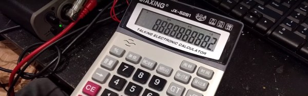
On his travels in China his attention was caught by an everyday electronic gadget, an electronic calculator that speaks the numbers and operations in Chinese as you use it. He bought a few of them, hoping that when he got them back to his bench he’d find an EEPROM containing the samples, which he could replace with his own for a cheap but low bitrate sampler.
Sadly this neat hack was not to be, for when he tore the surprisingly well-built calculators down he found only an epoxy blob concealing a single chip. All was not lost though, for while investigating the device’s features he discovered that as well as speaking Chinese numbers and operands it also had a selection of alarm tunes built-in, plus a mode in which it operated as a rudimentary electronic organ. He leaves us with a couple of videos we’ve posted below the break, first his teardown, and then a virtual orchestra of calculators playing dance music as he forgets the fail and concentrates on the win.
Continue reading “Fail Of The Week: Talking Chinese Calculator Synth Orchestra”