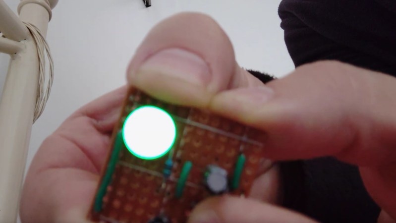
[Tito] entered a Self-Charging LED Flasher into the Component Abuse Challenge. It’s a simple re-build of a design by the unstoppable [Burkhard Kainka], and while [Tito] doesn’t explain its workings in detail, it’s a clever experiment in minimalism, and a bit of a head-scratcher at the same time.
You press a button and an LED flashes. But there is no battery, so how does it work? Maybe the schematic to the right here will help. Or does it confound? Look at it yourself before reading on and see if you can figure out how it works.
Keeping chickens in predator-prone areas demands serious fortifications, but even the most robust coop can become a hassle without automation. That’s where [lcamtuf] steps in with his Chicken Squisher 3000, a clever DIY automatic door mechanism that opens and closes based on ambient light levels.
The chicken coop he previously built did not include a mechanism to automatically close the inner door at night, meaning that arrangements would have to be made should [lcamtuf] want to leave town for a couple of days. Not wanting to go with a commercial option for this door as that would require a good deal of modifications to the original door setup, the Chicken Squisher 3000 adds minimal parts to the existing door to now open and close the door at dawn and dusk.
Using a 12 V DC motor with a gear reduction, he was able to generate more than enough torque to open and close the thick wooden door. Instead of a complex geared rack and pinion setup, [lcamtuf] has the motor mounted to a smooth rod that then applies force across the swing of the door attached with a rod end bearing. Driving the door’s automation is an AVR16DD14 microcontroller which is used to read the NSL-A6009 light sensor. [lcamtuf] uses a DRV8231 motor driver for controlling power going to that 12 V motor with the added benefit of being able to adjust stall torque to dial in a value strong enough to overcome the wooden door’s friction, but weak enough to not endanger any of his birds. There are also buttons on the metal enclosure used to override the light sensor should he want to override it manually.
Thanks, [lcamtuf], for sending in your latest weekend project; we love the resourcefulness of using just a handful of cheap parts to make a robust solution for your coop. If you haven’t seen them yet, be sure to check out some of our other chicken coop door hacks featured before.
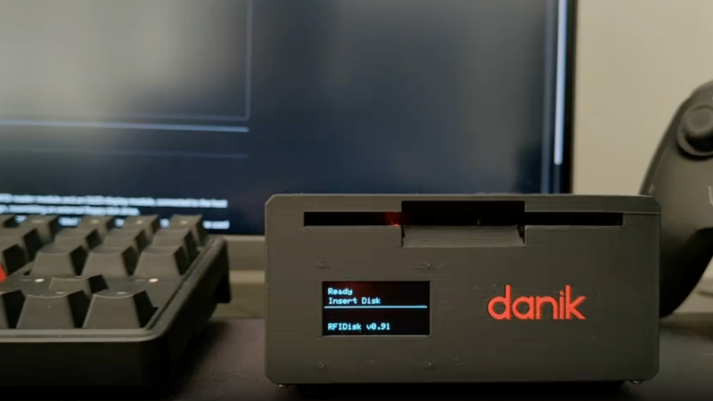
Not too long ago, part of using a computer was often finding the correct disk for the application you wanted to run and inserting it into your machine before you could start. With modern storage, this is largely a thing of the past. However, longing for some of that nostalgia, [ItsDanik] has been developing the RFIDisk, a 3D printed floppy drive that can kick off applications when their disk is inserted.
The desktop enclosure is printed to look like a standalone floppy drive, allowing use with either desktops or laptops. There’s the familiar 3.5 inch slot ready for your floppy disk, and there’s also a 1.3 in. OLED display on the front giving you feedback on the status of the RFIDisk — including telling you what’s currently inserted. Inside the enclosure is an Arduino Uno and an MFRC522 RFID reader. As the name would suggest, the way the RFIDisk enclosure reads its media is via NFC, not the traditional magnetic reader. Due to being RFID-based, the disks printed for the RFIDisk are solid without moving parts, but enclose a 25 mm NTAG213 NFC tag.
On the software side, [ItsDanik] has developed the RFIDisk Manager Python application, which is used to tie specific NFC tag IDs to commands to run when that tag is read. The application includes some nice features, such as being able to adjust the commands for both when the disk is first read and when it’s removed from the RFIDisk. You can also change what shows up on the OLED screen when the cartridge is inserted.
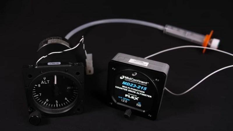
The old altimeter was entirely mechanical, except for a pair of wires which can power a backlight. Both the old and new altimeters have a dial on the front for calibrating the meter. The electronic altimeter has a connector on the back for integrating with the rest of the airplane. [Ben] notes that this particular electronic altimeter is only a backup in the airplane it is installed in, it’s there for a “second opinion” or in case of emergency.
Hyperspectral cameras aren’t commonplace items; they capture spectral data for each of their pixels. While commercial hyperspectral cameras often start in the tens of thousands of dollars, [anfractuosity] decided to make his own with the Waverider.
To capture spectral data from every pixel location in the camera, [anfractuosity] first needed a way to collect that data — for that, he used an AFBR-S20M2WV, a miniature USB spectrometer he picked up second-hand. This sensor allows for the collection of data from 225 nm all the way up to 1000 nm. Of course, the sensor can only do that for one single input, so to turn it into a camera, [anfractuosity] added a stepper-driven x-y stage controlled by a Raspberry Pi Pico and some TMC2130 stepper drivers.
Back in 1966, a suitable toy for a geeky kid was a radio kit. You could find simple crystal radio sets or some more advanced ones. But some lucky kids got the Philips Electronic Engineer EE8 Kit on Christmas morning. [Anthony Francis-Jones] shows us how to build a 2-transistor AM radio from a Philips Electronic Engineer EE8 Kit.
According to [The Radar Room], the kit wasn’t just an AM radio. It had multiple circuits to make (one at a time, of course), ranging from a code oscillator to a “wetness detector.”
The kit came with a breadboard and some overlays for the various circuits, along with the required components. It relied on springs, friction, and gravity to hold most of the components to the breadboard. A little wire is used, but mostly the components are connected to each other with their leads and spring terminals.
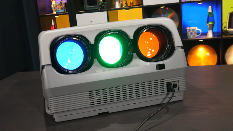
CRT monitors: there’s nothing quite like ’em. But did you know that video projectors used to use CRTs? A trio of monochrome CRTs, in fact: one for each color; red, green, and blue. By their powers combined, these monsters were capable of fantastic resolution and image quality. Despite being nowhere near as bright as modern projectors, after being properly set up, [Technology Connections] says it’s still one of the best projected images he has seen outside of a movie theatre.
After a twenty-minute startup to reach thermal equilibrium, one can settle down with a chunky service manual for a ponderous calibration process involving an enormous remote control. The reward is a fantastic (albeit brightness-limited) picture.
Still, these projectors had drawbacks. They were limited in brightness, of course. But they were also complex, labor-intensive beasts to set up and calibrate. On the other hand, at least they were heavy.
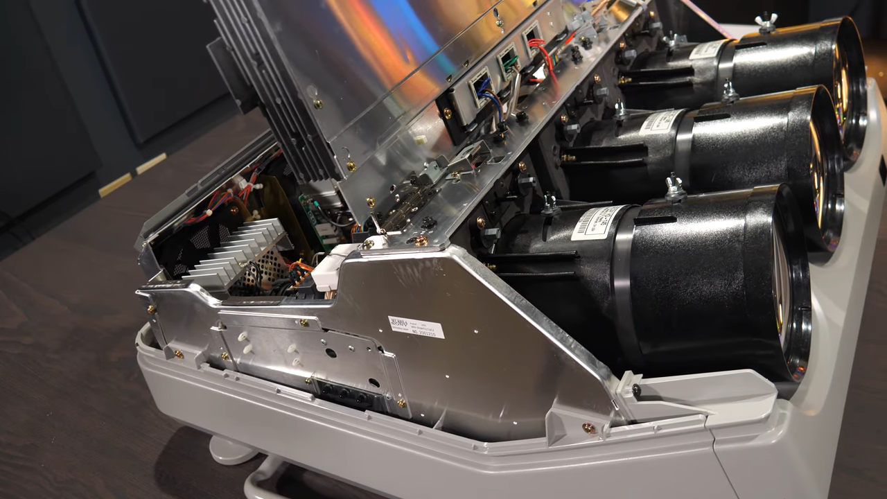
[Technology Connections] gives us a good look at the Sony VPH-D50HT Mark II CRT Projector in its tri-lobed, liquid-cooled glory. This model is a relic by today’s standards, but natively supports 1080i via component video input and even preserves image quality and resolution by reshaping the image in each CRT to perform things like keystone correction, thus compensating for projection angle right at the source. Being an analog device, there is no hint of screen door effect or any other digital artifact. The picture is just there, limited only by the specks of phosphor on the face of each tube.
Converging and calibrating three separate projectors really was a nontrivial undertaking. There are some similarities to the big screen rear-projection TVs of the 90s and early 2000s (which were then displaced by plasma and flat-panel LCD displays). Unlike enclosed rear-projection TVs, the screen for projectors was not fixed, which meant all that calibration needed to be done on-site. A walkthrough of what that process was like — done with the help of many test patterns and a remote control that is as monstrous as it is confusing — starts at 15:35 in the video below.
Like rear-projection TVs, these projectors were displaced by newer technologies that were lighter, brighter, and easier to use. Still, just like other CRT displays, there was nothing quite like them. And if you find esoteric projector technologies intriguing, we have a feeling you will love the Eidophor.

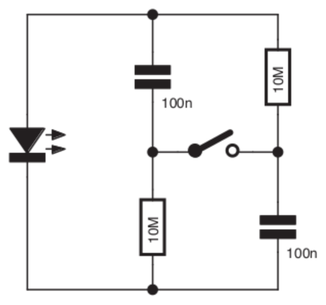 You press a button and an LED flashes. But there is no battery, so how does it work? Maybe the schematic to the right here will help. Or does it confound? Look at it yourself before reading on and see if you can figure out how it works.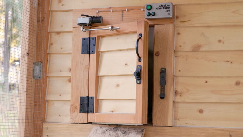

![[Anthony] holding the EE8 kit](https://hackaday.com/wp-content/uploads/2025/10/EE8-banner.jpg?w=600&h=450)