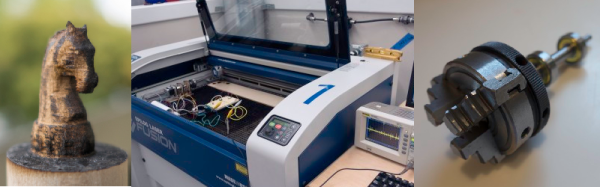
Actors want to be singers and singers want to be actors. The hacker equivalent to this might be that 3D printers want to be laser cutters or CNC machines and laser cutters want to be 3D printers. When [Kurt] and [Lawrence] discovered their tech shop acquired a 120 Watt Epilog Fusion laser cutter, they started thinking if they could coax it into cutting out 3D shapes. That question led them to several experiments that were ultimately successful.
The idea was to cut away material, rotate the work piece, and cut some more in a similar way to how some laser cutters handle engraving cylindrical objects. Unlike 3D printing which is additive, this process is subtractive like a traditional machining process. The developers used wood as the base material. They wanted to use acrylic, but found that the cut away pieces tended to stick, so they continued using wood. However, the wood tends to char as it is cut.
In the end, they not only had to build special jigs and electronics, they also had to port some third party control software to solve some issues with the Epilog Fusion cutter’s built in software. The final refinement was to use the laser’s raster mode to draw surface detail on the part.
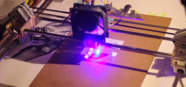
The results were better than you’d expect, and fairly distinctive looking. We’ve covered a similar process that made small chess pieces out of acrylic using two passes. This seems like a natural extension of the same idea. Of course, there are very complicated industrial machines that laser cut in three dimensions (see the video below), but they are not in the same category as the typical desktop cutter.
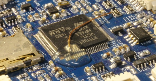

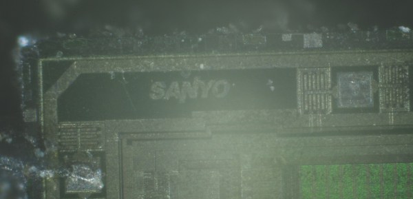
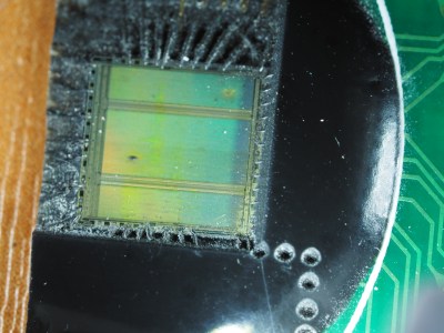 The lack of traces between the two pushed [Jamie’s] curiosity past the tipping point. He didn’t have access to any nitric acid which is used in the customary chemical decapping process. He did, however, have access to a laser cutter. It turns out that


