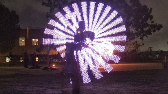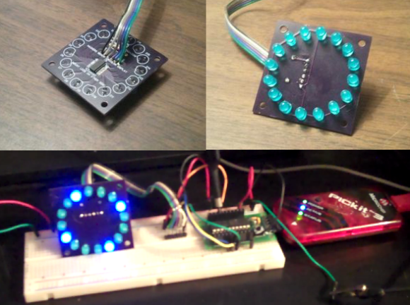
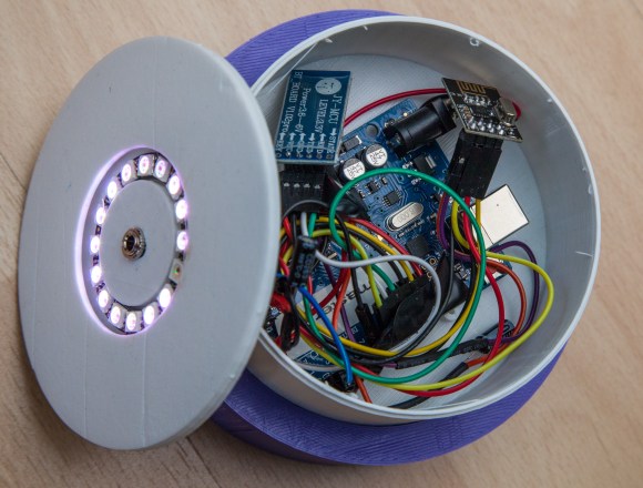
[Rob] created these amazing Bluetooth controlled LED lights for his daughter’s wedding adding a colorful ambient glow to the ceremony. Each item held a Neopixel ring and an Arduino microprocessor with a wireless module that could be individually addressed over a ‘mini-network.’ The main master station would receive commands from a Windows Phone. Usually we see Arduino-based projects being run with Android apps, so it’s nice to see that Microsoft is still present in the maker community.
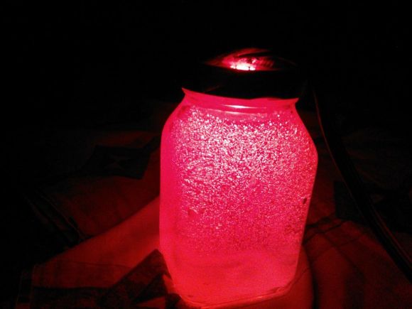
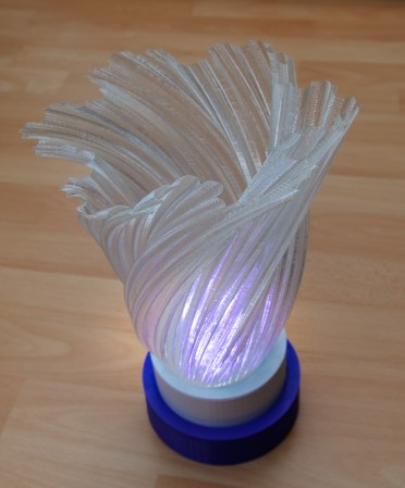
The enclosures and translucent vases that sit atop the devices were 3D printed. All eight of the matrimonial units synchronized with each other, and the colors could be changed by sliding the settings bar on the app. [Rob] says that it was a lot of fun to build, and jokingly stated that it kept him “out of all the less important aspects of the ceremony. (food choice, decor, venue, who to marry etc etc).” The outcome was a beautiful arrangement of tabletop lighting for the wedding. A demo of [Rob]’s setup can be seen in the video below.