What would you do if you had access to an industrial ABB IRB 6640 robot? We’d probably make a giant 3D printer, but if you’re [Jeff Crossman] and [Kevyn McPhail], you’d make one of the most advanced light painting setups we’ve ever seen.
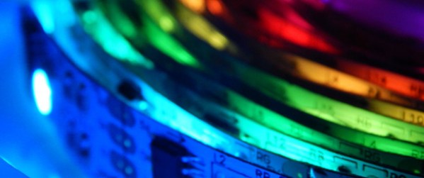
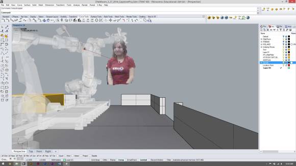
The setup itself is really quite simple — a single RGB LED is connected to a Teensy microcontroller on a tool-head for the robot — controlling the robot is the hard (fun?) part. To create the images, [Jeff] had several students come in to have their photographs taken using a Microsoft Kinect. This allowed him to create an RGB point cloud for the robot to recreate.
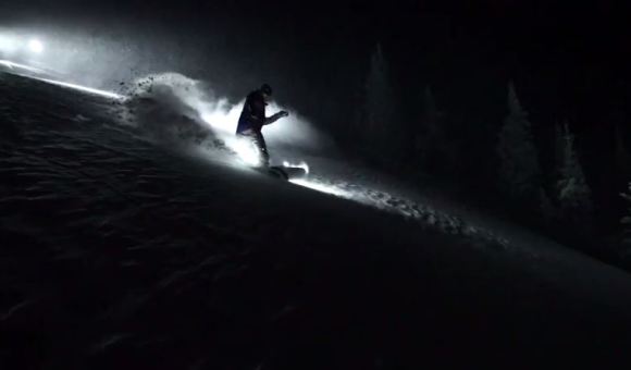
Using Rhino he created the tool paths required for the robot to build up a floating 3D image of the students for the camera taking the long exposure. Each demonstration made use of ~5000 points, which takes the robot arm about 25 minutes to place.
It’s a fascinating video, and yes it does seem like a bit of overkill, but hey — why not?
Continue reading “Industrial Light Painting Steps It Up A Few”