Controlling A Cute Ikea Night Light With Android On The Cheap

When [trandi]’s wife saw a cute night light at Ikea, she had to have it. She actually bought several of these for when her husband would inevitably crack one open and start tinkering with the microcontroller inside. The inevitable hack is pretty cool, and also gives us some ideas for interfacing with Android on the cheap.

The build started as an Ikea Spoka night light, an adorable anthropomorphized night light with a squishy silicone skin. Inside the Spoka are a dozen tri-color LEDs that [trandi] can cycle through with the push of a button. After deciding to control the lights inside the Spoka with an Android phone he reached for an IOIO Android breakout board. Fate intervened and [trandi] ended up with a ridiculously cheap Bluetooth modules that provides a simple serial connection to other Bluetooth devices.

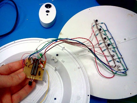
The build reuses the blue, red, orange LEDs in the night light but replaces the no-name 8-pin micro with an ATtiny2313. [Trandi] wrote a small Android app to control the color over a Bluetooth serial connection. Check out his demo after the break.

Continue reading “Controlling A Cute Ikea Night Light With Android On The Cheap”

Tool Box Light Dimmer Helps Out A Friend, Offers Up Design Tips

toolbox-lighting

[miceuz] has a friend that works as a theatre technician, and in the course of his job he often needs to jigger with various stage components while shows are in progress. As you can imagine, the lighting situation is far from ideal, so he asked [miceuz] to build him an adjustable lighting solution for his tool box.

The circuit itself is relatively straightforward, using an ATMega88 to provide the PWM required for dimming and color control. Input is taken from three different sources, a rotary encoder for color selection, a pot for brightness control, and a button to turn the light strip on and off.

[miceuz] says that while project came together pretty easily, it still presented some issues along the way which provide some useful design reminders for beginners (and some veterans) alike.

First and foremost: debounce, debounce, debounce. [miceuz] forgot this mantra and made a mad dash to add capacitors to his design after etching the PCB to ensure that his inputs were not bouncing all over the place. He also noted that one should always be sure to read the ADCL before the ADCH register when decoding ADC data. His final observation is that using thick traces is the best policy whenever possible – he ran into a lot of issues with traces detaching during assembly, which he had to rework with wire and solder.

In the end, his friend was happy with the result, and [miceuz] is a better hacker for having worked through his issues. What sorts of important/useful lessons have you learned through the course of your projects? Be sure to share them with us in the comments.

Building A LED Strip The Minimal Way

For his first big build with an MSP430, [Javon] decided to an RGB LED fader. Having worked with Arduinos in the past, he figured that his MSP430 would have a few PWM channels. After being proved wrong by the data sheet, [Javon] needed to figure out a way to switch a bunch of RGB LEDs with only one PWM channel on his microcontroller.

Because there was only one PWM pin on [Javon]’s micro, he needed a way to multiplex his output. He ended up using a 74HC4052 mux/demux chip to drive 20 LEDs. The LEDs were mounted onto hard board and the main part of the circuit built on a bit of perfboard. While there’s no total cost for his build, we’re guessing [Javon] didn’t spend much on his project; certainty much less than this explosion of LEDs.

[Javon] put all the build pictures up as a Google+ album and a few video demos up. Check those out after the break (009 Sound System warning, you might want to hit mute).

Continue reading “Building A LED Strip The Minimal Way”

Rainbow Machine Livens Up Any Photograph

rainbow-machine

[Shameel Arafin, Sean McIntyre, and Reid Bingham] really dig rainbows. Going by the moniker the “RainBroz”, the trio built a portable display that can be used to add cool light painting effects to pictures.

The group brings their Rainbow Machine all over the place, including parties, gatherings, and random spots on the street. Anyone is welcome to have their picture taken with the Rainbow machine, and each subject is given a card with a URL on it, so that they can check out their picture whenever they please.

The display consists of addressable RGB LED strips and an Arduino from Adafruit, along with the associated support mechanisms for moving the LEDs. The real magic is carried out by the LPD8806 light painting library, also from Adafruit, which enables the RainBroz to create all sorts of images with little fuss.

As you can see in the video below, the Rainbow Machine seems to get a pretty warm reception from just about everyone, even people grabbed right off the street. It looks simple enough to build, so why not put one together for your next gathering?

Continue reading “Rainbow Machine Livens Up Any Photograph”

Rainbow Board Of Many Ping-pong Balls

[George] just finished his first project: an 8×8 matrix “Board of Many Ping-Pong Balls” with 64 RGB LEDs. He started this project when he was 14 years old and finished the build over this last Christmas break. We won’t make any presumptions about [George]’s age, but we couldn’t think of a better project to start out on.

For the build, [George] used a Colorduino LED driver shield for his Arduino. This made the wiring simple, but the finished product is where this project really shines. For the base, [George] got a board laser cut at his school and used ping-pong balls to diffuse the LEDs. We’ve seen this many times but with this build there’s a neat way to drill a hole in a ping-pong ball; simply put the drill into reverse. The friction is enough to open the ball up, and the chips of plastic come outside instead of remaining in.

We’re really impressed with [George] and his winter break project. He’s lucky enough to have access to a laser cutter at school, and from a look at his monitor, he’s reading the right websites. You can check out his demo rainbow pattern after the break.

Continue reading “Rainbow Board Of Many Ping-pong Balls”

Minimalist RGB LED Cube Has A Very Short BoM

charlieplexed-led-cube

[Asher Glick] wrote in to share a project he has been working on with his friend [Kevin Baker], a 4x4x4 RGB LED cube. The pair are students at Rensselaer Polytechnic Institute and also members of the newly-formed Embedded Hardware Club on campus. As their first collaborative project, they decided to take on the ubiquitous LED cube, trimming down the component count to nothing more than 64 LEDs, a protoboard, some wire, and a single Arduino.

Many cubes we have seen use shift registers or decade counters to account for all the I/O required to drive so many LEDs. Their version of the cube has none of these extra components, solely relying on 16 of the Arduino’s I/O pins for control instead. You might notice something a bit different about the structure of their cube as well. Rather than using a grid of LEDs like we see in most Charlieplexed cubes, they constructed theirs using 16 LED “spires”, tucking the additional wiring underneath the board.

The result looks great, as you can see in the videos below. The cube looks pretty easy to build, and with a cost around $60 it is a reasonably cheap project as well.

Nice job, we look forward to seeing all sorts of fun projects from the Embedded Hardware Club in the future!

Continue reading “Minimalist RGB LED Cube Has A Very Short BoM”

Followup: Reproducing Impossible Circuits

Last month we caught wind of an impressive display of troll physics. [Fredzislaw100] out of Poland posted a video of a circuit that should not exist. As expected, the comments in our coverage blew up with 200 posts. About half the commenters called a little Adobe After Effects trickery, while the other half offered up an electrical explanation. We’re happy to report that [Alan] successfully reproduced the impossible circuit and earned an incredible amount of electronic wizard points in the process.

[Alan]’s solution uses low-frequency AC with the first two LEDs. The first LED points forwards and the second diode is reversed. Easy enough. For the third LED, [Alan] used high frequency AC with an inductor wired in parallel with the LED and the third switch. For those of you keeping track, that means [Fredzislaw100] put an SMD diode in two LEDs and two switches and an inductor in one LED and one switch.

[Alan]’s build is just a proof of concept – It’s still on a breadboard and doesn’t have the incredible level of polish that [Fredzislaw100]’s has. That being said, [Alan]’s build is most likely very similar given the small glitch at 2:05 in the original video.

Check out [Alan]’s build video below, and for an added treat check out his 2011 Advent Calendar of Circuits.

Continue reading “Followup: Reproducing Impossible Circuits”