Starter motors aren’t typically a great choice for motorized projects, as they’re designed to give engines a big strong kick for a few seconds. Driving them continuously can often quickly overheat them and burn them out. However, [Austin Blake] demonstrates that by choosing parts carefully, you can indeed have some fun with a starter motor-powered ride.
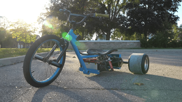
[Austin] decided to equip his drift trike with a 42MT-equivalent starter motor typically used in heavy construction machinery. The motor was first stripped of its solenoid mechanism, which is used to disengage the starter from an engine after it has started. The housing was then machined down to make the motor smaller, and a mount designed to hold the starter on the drift trike’s frame.
A 36V battery pack was whipped up using some cells [Austin] had lying around, and fitted with a BMS for safe charging. The 12V starter can draw up to 1650 amps when cranking an engine, though the battery pack can only safely deliver 120 amps continuously. A Kelly controller for brushed DC motors was used, set up with a current limit to protect the battery from excessive current draw.
The hefty motor weighs around 50 pounds, and is by no way the lightest or most efficient drive solution out there. However, [Austin] reports that it has held up just fine in 20 minutes of near-continuous testing, despite being overvolted well beyond its design specification. The fact it’s operating at a tenth of its rated current may also have something to do with its longevity. It also bears noting that many YouTube EVs die shortly after they’re posted. Your mileage may vary.
For a more modern solution, you might consider converting an alternator into a brushless electric motor. Video after the break.
Continue reading “Heavy-Duty Starter Motor Powers An Awesome Drift Trike”