Listening to police and fire calls used to be a pretty simple proposition: buy a scanner, punch in some frequencies — or if you’re old enough, buy the right crystals — and you’re off to the races. It was a pretty cheap and easy hobby, all things considered. But progress marches on, and with it came things like trunking radio and digital modulation, requiring ever more sophisticated scanners, often commanding eye-watering prices.
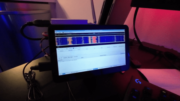
Having had enough of that, [Top DNG] decided to roll his own digital trunking scanner on the cheap. The first video below is a brief intro to the receiver based on the combination of an RTL-SDR dongle and a Raspberry Pi 5. The Pi is set up in headless mode and runs sdrtrunk, which monitors the control channels and frequency channels of trunking radio systems, as well as decoding the P25 digital modulation — as long as it’s not encrypted; don’t even get us started on that pet peeve. The receiver also sports a small HDMI touchscreen display, and everything can be powered over USB, so it should be pretty portable. The best part? Everything can be had for about $250, considerably cheaper than the $600 or so needed to get into a purpose-built digital trunking scanner — we’re looking at our Bearcat BCD996P2 right now and shedding a few tears.
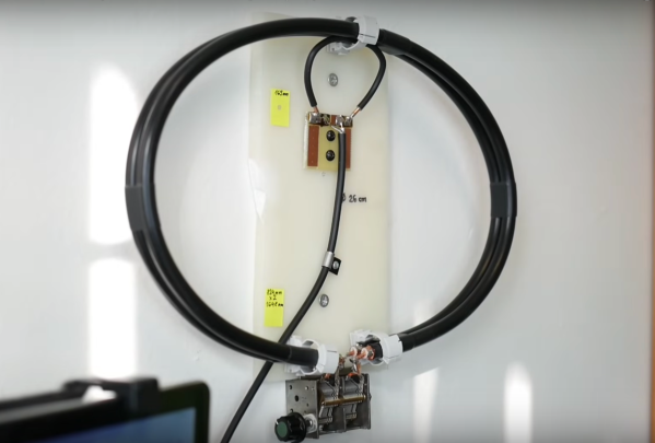
The second video below has complete details and a walkthrough of a build, from start to finish. [Top DNG] notes that sdrtrunk runs the Pi pretty hard, so a heat sink and fan are a must. We’d probably go with an enclosure too, just to keep the SBC safe. A better antenna is a good idea, too, although it seems like [Top DNG] is in the thick of things in Los Angeles, where LAPD radio towers abound. The setup could probably support multiple SDR dongles, opening up a host of possibilities. It might even be nice to team this up with a Boondock Echo. We’ve had deep dives into trunking before if you want more details.
Continue reading “Pi 5 And SDR Team Up For A Digital Scanner You Can Actually Afford” →