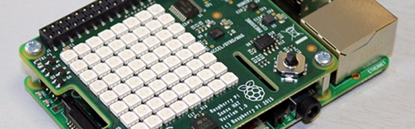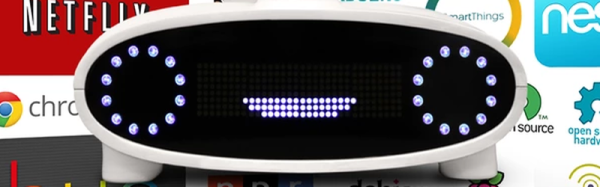
The Amazon Echo is an attempt to usher in a new product category. A box that listens to you and obeys your wishes. Sort of like Siri or Google Now for your house. Kickstarter creator [Joshua Montgomery] likes the idea, but he wants to do it all Open Source with a Raspberry Pi and an Arduino.
The Kickstarter (which reached its funding goal earlier this month) claims the device will use natural language to access media, control IoT devices, and will be open both for hardware and software hacking. The Kickstarter page says that Mycroft has partnerships with Lucid and Canonical (the people behind Ubuntu). In addition, they have added stretch goals to add computer vision and Linux desktop control to Mycroft.

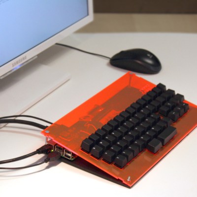 The source code, an image for the Pi 2, and directions for making it all work are available. [Lukas] also describes how to get a new OS up and running on a Pi.