A Brief History Of Cyrix, Or How To Get Sued By Intel A Lot

In a new installment on computer history, [Bradford Morgan White] takes us through the sordid history of Cyrix, as this plucky little company created the best math co-processors (FasMath) and then a range of interesting x86-compatible CPUs that would give competing x86 CPUs a run for their money. Even though Cyrix played by the rules of licensing agreements, Intel would keep suing Cyrix repeatedly since the 1980s well into 1990s, for a total of seventeen times until Cyrix counter-sued for patent violations in May of 1997.

This case was settled between Cyrix and Intel, with a cross-licensing agreement established. Unfortunately these mounting legal costs and the stresses of keeping up with the competition (i.e. Intel) was proving too much and Cyrix was sold off to National Semiconductor, who wasn’t enthusiastic about competing with Intel. After this Cyrix got split up into Geode (sold to AMD) and Cyrix Technologies (sold to VIA). Interestingly, VIA’s x86 patent licenses and patents ended up being the foundation of Zhaoxin: a joint venture between VIA and Shanghai’s government which produces x86 CPUs for primarily the Chinese market.

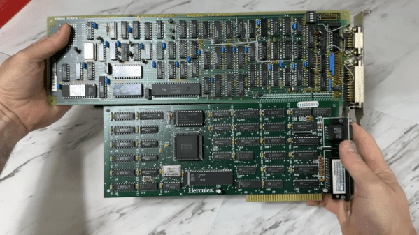
We looked at the Cyrix Cx486DLC processor a while ago, and why their 386 upgrade options were perhaps not that great. Their later CPUs have however left a strong legacy that seems to endure in some way to this day.

Z80 Testing The 80s Way

According to [MTSI], if you used a Z80 chip back in the 1980s, it almost certainly passed through the sole Fairchild Sentry 610 system that gave it the seal of approval.

The Sentry was big iron for its day. The CPU was a 24-bit device and ran at a blistering 250 kHz. Along with a tape drive and a specialized test bed, it could test Z80s, F8s, and other Mostek products of the day. There was a disk drive, too. The 26-inch platters stored under 10 kilobytes. Despite the relatively low speed of the CPU, the Sentry could test devices running up to 10 MHz, which was plenty for the CPUs it was testing. The actual test interface ran at 11 MHz and used an exotic divider to generate slower frequencies.

According to the post, an informal count of the number of chips in the device came up with around 60,000. That, as you might expect, took a huge power supply, too.

Continue reading “Z80 Testing The 80s Way”

The 1987 Videonics Editing System

Videonics: The Dawn Of Home Video Editing, Revisited

Here’s a slice of history that will make any retro-tech fan grin: before TikTok and iMovie, there was a beast called the Videonics DirectED Plus. This early attempt at democratizing video editing saved enthusiasts from six-figure pro setups—but only barely. Popular Science recently brought this retro marvel back to life in a video made using the very system that inspired it. Picture it: 1987, VHS at its peak, where editing your kid’s jazz recital video required not just love but the patience of a saint, eight VCRs, three Videonics units, two camcorders, and enough remotes to operate a space shuttle.

The Videonics DirectED Plus held promise with a twist. It offered a way to bypass monstrous editing rigs, yet mastering its panel of buttons felt like deciphering hieroglyphs. The ‘Getting Started’ tape was the analog era’s lifeline, often missing and leaving owners hunting through second-hand stores, forgotten basements, and enthusiast forums. Fast forward to today, and recreating this rig isn’t just retro fever—it’s a scavenger hunt.

The 1987 Videonics Editing SystemOnce assembled, the system resembled a spaghetti junction of cables and clunky commands. One wrong button press could erase precious minutes of hard-won footage. Still, the determination of DIY pioneers drove the machine’s success, setting the stage for the plug-and-play ease we now take for granted.

These adventures into retro tech remind us of the grit behind today’s seamless content creation. Curious for more? Watch the full journey by Popular Science here.

Continue reading “Videonics: The Dawn Of Home Video Editing, Revisited”

Building A Motor Feed For The UE1 Vacuum Tube Computer’s Paper Tape Reader

Building a paper tape reader by itself isn’t super complicated: you need a source of light, some photoreceptors behind the tape to register the presence of holes and some way to pull the tape through the reader at a reasonable rate. This latter part can get somewhat tricky, as Usagi Electric‘s [David Lovett] discovered while adding this feature to his vacuum tube-era DIY reader. This follows on what now seems like a fairly simple aspect of the photosensors and building a way to position said photosensors near the paper tape.

As the feed rate of the paper tape is tied to the reading speed, and in the case of [David]’s also contains the clock for the custom tube-based UE1 computer, it determines many of the requirements. With 8 bits per line, the tape forms the ROM for the system, all of which has to be executed and used immediately when read, as there is no RAM to load instructions into. This also necessitates the need to run the tape as an endless loop, to enable ‘jumping’ between parts of this paper-based ROM by simple masking off parts of the code until the desired address is reached.

For the motor a slot car motor plus speed-reduction gear was chosen, with a design to hold these then designed in FreeCAD. Courtesy of his brother’s hobby machine shop and a CAD professional’s help, producing these parts was very easy, followed by final assembly. Guides were added for the tape, not unlike with a cassette player, which allowed the tape to be pulled through smoothly. Next up is wiring up the photodiodes, after which theoretically the UE1 can roar into action directly running programs off paper tape.

Continue reading “Building A Motor Feed For The UE1 Vacuum Tube Computer’s Paper Tape Reader”

[rasteri] holding his HIDMan USB dongle

HIDman Brings Modern Input To Vintage PCs

Retro computing enthusiasts, rejoice! HIDman, [rasteri]’s latest open source creation, bridges the gap between modern USB input devices and vintage PCs, from the IBM 5150 to machines with PS/2 ports. Frustrated by the struggle to find functioning retro peripherals, [rasteri] developed HIDman as an affordable, compact, and plug-and-play solution that even non-techies can appreciate.

The heart of HIDman is the CH559 microcontroller, chosen for its dual USB host ports and an ideal balance of power and cost-efficiency. This chip enables HIDman’s versatility, supporting serial mice and various keyboard protocols. Building a custom parser for the tricky USB HID protocol posed challenges, but [rasteri]’s perseverance paid off, ensuring smooth communication between modern devices and older systems.

Design-wise, the project includes a thoughtful circuit board layout that fits snugly in its case, marrying functionality with aesthetics. Retro computing fans can jump in by building HIDman themselves using the files in the GitHub repository, or by opting for the ready-made unit.

Continue reading “HIDman Brings Modern Input To Vintage PCs”

Retrotechtacular: Computer-Generate Video 1968 Style!

[Classic Microcomputers] read in a book that there was a computer-generated film made in the late 1960s, and he knew he had to watch it. He found it and shared it along with some technical information in the video below.

Modern audiences are unlikely to be wowed by the film — Permutations — that looks like an electronic spirograph. But for 1968, this was about as high tech as you could get. The computer used was an IBM mainframe which would have cost a fortune either to buy or to rent the hours it would take to make this short film. Now, of course, you could easily replicate it on even your oldest PC. In fact, we are surprised we haven’t seen any recreations in the demoscene.

Continue reading “Retrotechtacular: Computer-Generate Video 1968 Style!”

Hear A Vintage Sound Chip Mimic The Real World

Sound chips from back in the day were capable of much more than a few beeps and boops, and [InazumaDenki] proves it in a video recreating recognizable real-world sounds with the AY-3-8910, a chip that was in everything from arcade games to home computers. Results are a bit mixed but it’s surprising how versatile a vintage sound chip that first came out in the late 70s is capable of, with the right configuration.

Recreating a sound begins by analyzing a spectrograph.

Chips like the AY-3-8910 work at a low level, and rely on being driven with the right inputs to generate something useful. It can generate up to three independent square-wave tones, but with the right approach and setup that’s enough to get outputs of varying recognizability for a pedestrian signal, bird call, jackhammer, and referee’s whistle.

To recreate a sound [InazumaDenki] begins by analyzing a recording with a spectrogram, which is a visual representation of frequency changes over time. Because real-world sounds consist of more than just one frequency (and the AY-3-8910 can only do three at once), this is how [InazumaDenki] chooses what frequencies to play, and when. The limitations make it an imperfect reproduction, but as you can hear for yourself, it can certainly be enough to do the job.

How does one go about actually programming the AY-3-8910? Happily there’s a handy Arduino AY3891x library by [Andreas Taylor] that makes it about as simple as can be to explore this part’s capabilities for yourself.

If you think retro-styled sound synthesis might fit into your next project, keep in mind that just about any modern microcontrollers has more than enough capability to do things like 80s-style speech synthesis entirely in software.

Continue reading “Hear A Vintage Sound Chip Mimic The Real World”