A few months ago, a very inexpensive 3D printer appeared on Monoprice. My curiosity for this printer was worth more than $200, so I picked one of these machines up. The Monoprice MP Select Mini is an awesome 3D printer. It’s the perfect printer to buy for a 13-year-old who might be going through a ‘3D printing phase’. It’s a great printer to print a better printer on. This printer is a sign the 3D printing industry is not collapsing, despite Makerbot, and foreshadows the coming age of consumer 3D printers.
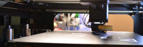
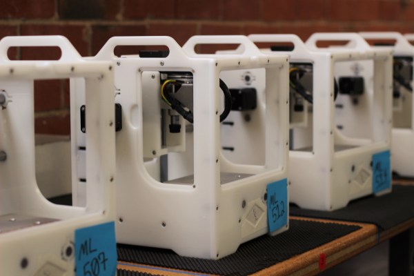
The MP Select Mini isn’t Monoprice’s only 3D printer; the printer I bought was merely the ‘good’ printer in the good-better-best lineup. Since my review of the MP Select Mini, Monoprice has introduced their top of the line, the Maker Ultimate 3D printer. Monoprice asked if I would like to take a look at this offering, and I’m more than happy to oblige.
After a week of burn-in, I can safely say you’re not wasting your money on this $700 3D printer. It’s not a starter printer — it’s one that will last you a long time. 2016 is the beginning of the age of consumer 3D printers, and the Monoprice Maker Ultimate is more than proof of this.
I learned some basic electronics in high school physics class: resistors, capacitors, Kirchhoff’s law and such, and added only what was required for projects as I did them. Then around 15 years ago I decided to read some books to flesh out what I knew and add to my body of knowledge. It turned out to be hard to find good ones.
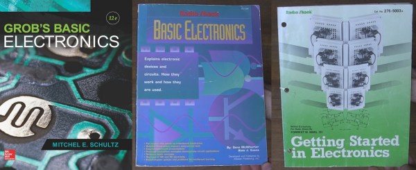
The electronics section of my bookcase has a number of what I’d consider duds, but also some gems. Here are the gems. They may not be the electronics-Rosetta-Stone for every hacker, but they are the rock on which I built my church and well worth a spot in your own reading list.
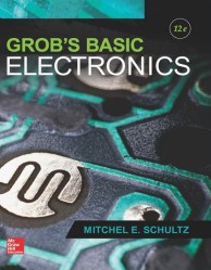
Grob’s Basic Electronics
Grob’s Basic Electronics 12th Edition
Grob’s Basic Electronics by Mitchel E Schultz and Bernard Grob is a textbook, one that is easy to read yet very thorough. I bought mine from a used books store. The 1st Edition was published in 1959 and it’s currently on the 12th edition, published in 2015. Clearly this one has staying power.
I refer back to it frequently, most often to the chapters on resonance, induction and capacitance when working on LC circuits, like the ones in my crystal radios. There are also things in here that I couldn’t find anywhere else, including thoroughly exhaustive online searches. One such example is the correct definitions and formulas for the various magnetic units: ampere turns, field intensity, flux density…
I’d recommend it to a high school student or any adult who’s serious about knowing electronics well. I’d also recommend it to anyone who wants to reduce frustration when designing or debugging circuits.
Series-Resonance calculations
Series-Resonance schematic
You can find the table of contents here but briefly it has all the necessary introductory material on Ohm’s and Kirchhoff’s laws, parallel and series circuits, and so on but to give you an idea of how deep it goes it also has chapters on network theorems and complex numbers for AC circuits. Interestingly my 1977 4th edition has a chapter on vacuum tubes that’s gone in the current version and in its place is a plethora of new ones devoted to diodes, BJTs, FETs, thyristors and op-amps.
You can also do the practice problems and self-examination, just to make sure you understood it correctly. (I sometimes do them!) But also, being a textbook, the newest edition is expensive. However, a search for older but still recent editions on Amazon turns up some affordable used copies. Most of basic electronics hasn’t changed and my ancient edition is one of my more frequent go-to books. But it’s not the only gem I’ve found. Below are a few more.
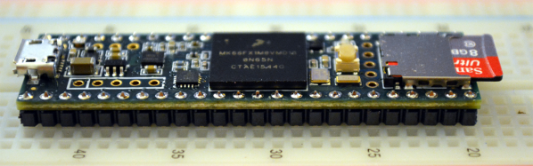
Paul Stoffregen has built a new Teensy. The latest in the line of very powerful, USB-capable microcontrollers is the Teensy 3.5 and 3.6 development boards. It’s faster, more capable, and bigger putting even more pins on a solderless breadboard.
The first Teensy was one of the first Arduino compatible boards with native USB. The Teensy 2.0 was even better with support for USB keyboards, mice, and MIDI. Even today, the Teensy 2.0 is the de facto board to use if you want to build anything like a USB keyboard. The Teensy 2.0 was followed by the exceptionally powerful Teensy 3.0, the first 32-bit Arduino compatible board, and thanks to Paul’s contributions of a pile of Arduino libraries, doing cool stuff faster has never been easier. Since the launch of the Teensy 3.0, its successors, the 3.1 and 3.2 have launched. If you want the power of an ARM microcontroller with the deepest Arduino library support, there’s only one board you should consider.
I’ll admit. When I saw the Othermill for the first time I thought it was just another mill with cheap Chinese hardware inside sold as a premium. I’m ashamed to say that I even trash talked it a little bit. It gave me another chance to relearn that I should always do my research before being a jerk, check my assumptions thoroughly, and even then it’s not recommended. Other Machine Company was kind enough to let me swing by the office in Berkeley California. [Danielle], the CEO, led me through the design of the mill as well as the challenges in running the operation.
The Othermill is a serious machine, and with the recent release of the Othermill Pro, it’s only getting better. The components are not bargain basement. This is something that could be more obvious, but it’s almost entirely made from US sourced parts, including the custom stepper motors. There aren’t any ball bearings that will start to make strange noises in a year. It can now cut 6mil traces in a PCB all day long. To put it into perspective. The Othermill Pro costs a third of the price of an equivalent machine from LPKF and has the same capabilities.
Psst… Wanna make a canning jar diode? A tennis ball triode? How about a semiconductor transistor? Or do you just enjoy sitting back and following along an interesting narrative of something being made, while picking up a wealth of background, tips and sparking all sorts of ideas? In my case I wanted to make a cuprous oxide semiconductor diode and that lead me to H.P. Friedrichs’ wonderful book Instruments of Amplification. It includes such a huge collection of amplifier knowledge and is a delight to read thanks to a narrative style and frequent hands-on experiments.
My well worn copy of Instruments of Amplifications
DIY point-contact semiconductor transistor
Friedrichs first authored another very popular book, The Voice of the Crystal, about making crystal radios, and wanted to write a second one. For those not familiar with crystal radios, they’re fun to make radios that are powered solely by the incoming radio waves; there are no batteries. But that also means the volume is low.
Readers of that book suggested a good follow-up would be one about amplifier circuits, to amplify the crystal radio’s volume. However, there were already an abundance of such books. Friedrichs realized the best follow-up would be one on how to make the amplifying components from scratch, the “instruments of amplification”. It would be unique and in the made-from-scratch spirit of crystal radios. The book, Instruments of Amplification was born.
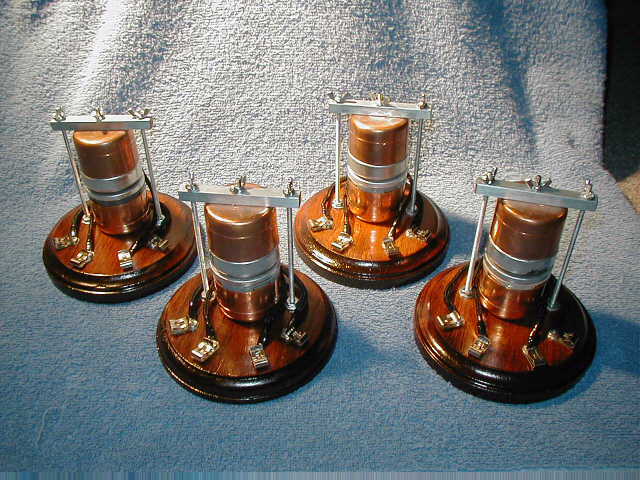
The book includes just the right amount of a history, giving background on what an amplifier is and how they first came in the electrical world. Telegraph operators wanted to send signals over greater and greater distances and the solution was to use the mix of electronics and mechanics found in the telegraph relay. This is the springboard for his first project and narrative: the microphonic relay.
The microphonic relay example shown on the right places a speaker facing a microphone; the speaker is the input with the microphone amplifying the output. He uses a carbon microphone salvaged from an old telephone headset, housing everything in an enclosure of copper pipe caps, steel bar stock, nuts and bolts mounted on an elegant looking wood base. All the projects are made with simple parts, with care, and they end up looking great.
I just had my car in for an inspection and an oil change. The garage I take my car to is generally okay, they’re more honest than a stealership, but they don’t cross all their t’s and dot all their lowercase j’s. A few days after I picked up my car, low and behold, I noticed the garage didn’t do a complete oil change. The oil life indicator wasn’t reset, which means every time I turn my car on, I’ll have to press a button to clear an ominous glowing warning on my dash.
For my car, resetting the oil life indicator is a simple fix – I just need to push the button on the dash until the oil life indicator starts to blink, release, then hold it again for ten seconds. I’m at least partially competent when it comes to tech and embedded systems, but even for me, resetting the oil life sensor in my car is a bit obtuse. For the majority of the population, I can easily see this being a reason to take a car back to the shop; the mechanic either didn’t know how to do it, or didn’t know how to use Google.
The two most technically complex things I own are my car and my computer, and there is much more information available on how to fix or modify any part of my computer. If I had a desire to modify my car so I could read the value of the tire pressure monitors, instead of only being notified when one of them is too low, there’s nowhere for me to turn.
2015 was the year of car hacks, ranging from hacking ECUs to pass California emissions control standards, Google and Tesla’s self-driving cars, to hacking infotainment systems to drive reporters off the road. The lessons learned from these hacks are a hodge-podge of forum threads, conference talks, and articles scattered around the web. While you’ll never find a single volume filled with how to exploit the computers in every make and model of automobile, there is space for a reference guide on how to go about this sort of car hacking.
I was given the opportunity to review The Car Hacker’s Handbook by Craig Smith (259p, No Starch Press). Is it a guide on how to plug a dongle into my car and clear the oil life monitor the hard way? No, but you wouldn’t want that anyway. Instead, it’s a much more informative tome on penetration testing and reverse engineering, using cars as the backdrop, not the focus.
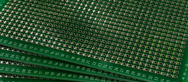
Back in 2015 [Ben Wang] attempted to re-invent the protoboard with the Perf+. Not long afterward, some improvements (more convenient hole size and better solder mask among others) yielded an updated version which I purchased. It’s an interesting concept and after making my first board with it here are my thoughts on what it does well, what it’s like to use, and what place it might have in a workshop.
Perf+ Overview
One side of a Perf+ board. Each hole can selectively connect to the bus next to it with a solder bridge. These bus strips are vertical. The ones on the back are horizontal.
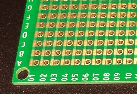
The Perf+ is two-sided perfboard with a twist. In the image to the left, each column of individual holes has a bus running alongside. Each hole can selectively connect to its adjacent bus via a solder bridge. These bus traces are independent of each other and run vertically on the side shown, and horizontally on the back.
Each individual hole is therefore isolated by default but can be connected to one, both, or neither of the bus traces on either side of the board. Since these traces run vertically on one side and horizontally on the other, any hole on the board can be connected to any other hole on the board with as few as two solder bridges and without a single jumper wire.
It’s an innovative idea, but is it a reasonable replacement for perfboard or busboard? I found out by using it to assemble a simple prototype.