[Alvaro Prieto]’s talk at the Hackaday Supercon began with a slide that asks the rhetorical question “Why Laser-Shooting Robots?” Does a rhetorical question need an answer? [Alvaro] gives one anyway: “Because lasers are awesome.” We concur.
But it doesn’t hurt that DEFCON holds a laser robot contest to give you an excuse, either. You see, [Alvaro]’s laser-wielding robot was the First Place finisher in the 2014 DEFCONBOTS contest, and a much more ambitious design came in third in 2015. His Supercon talk is all about the lessons he’s learned along the way, because that’s really the point of these contests anyway, right?
“I have no idea what I’m doing.”
[Alvaro] started off with a disclaimer, but when [Alvaro] says he doesn’t know what he’s doing, what he means is that he hasn’t received formal training in building laser-wielding, autonomous turret robots. (How did we miss that class in school?)
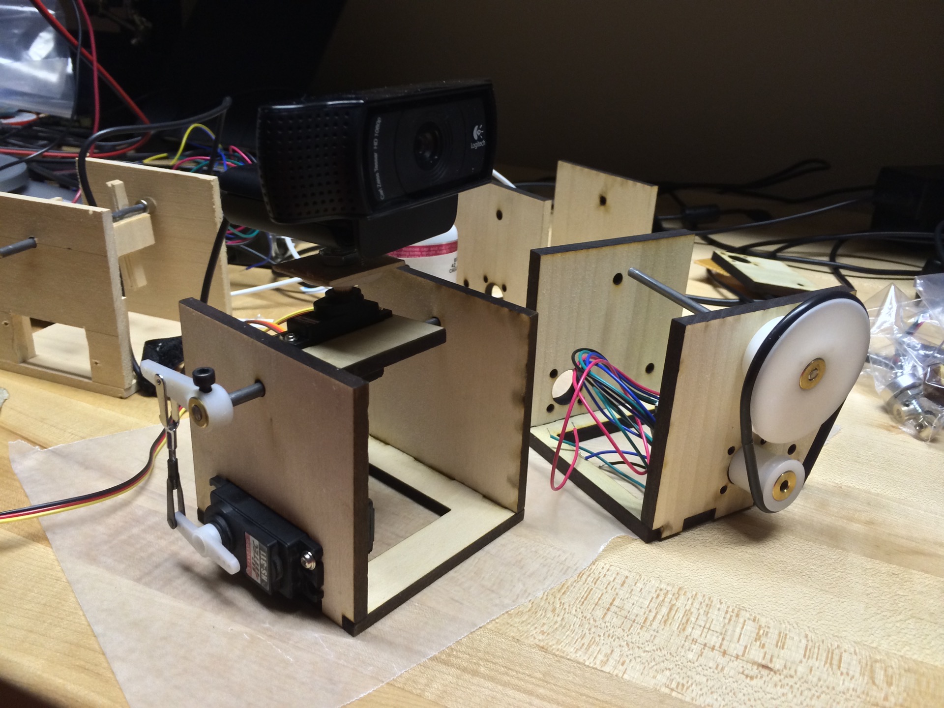
He’s a true hacker, though; he didn’t know what he was doing when he started out but he started out anyway. [Alvaro]’s takes us from the first prototypes where he used servo motors with inadequate angular resolution mounted to balsa wood frames that he (obviously) cut with a knife by hand, through laser-cut frames with custom gearing and stepper motors, all the way to his DEFCONBOTS 2015 entry, based on OpenBeam aluminum extrusions and using professional laser-show galvos capable of swinging the beam around to thousands of points per second.