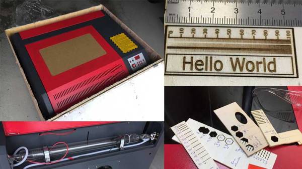
This is the future and we live in a world of 3D printers and laser cutters. Have you ever pondered the question of getting yourself a laser cutter? Well [Erich Styger] just landed a 50 Watt Laser Cutter from AliExpress and has written up a detailed guide to his experience.
[Erich] had been wrestling with the idea of buying one for himself for some time but was put off by the difficulty in their operation. This changed when [Scorch] published the K40 Whisperer control software which allows for better control over these machines. With the hopes of an interesting weekend project, [Erich Styger] took a leap of faith and spent $900 on a model 4040 laser cutter.
In his blog, he goes through the steps in setting up the machine as well as calibrating the laser. With a plethora of images and a detailed look at each aspect of the leveling and testing, [Erich Styger] had a weekend well spent and a working K40 laser cutter for his workshop. But perhaps the more valuable part of the stories is the overall experience.
It was not a “what you see is what you get” order, but it did turn out to be a hacker’s “what you want is what you get” adventure. The machine didn’t look the same as the picture, it came with a burned CD-R with a box full of small parts (in addition to separate shipment of a USB thumb drive and silicone sealant), and there were some mechanical touchups plus a stuck switch requiring reassembly. He has done an excellent job of documenting from order to test-runs and the photos alone are worth taking a look.
Adding value to inexpensive laser cutters in an often-featured project around here. If you are looking for more details on these wonderful machines, be sure to check out more tales of Cheap Laser Cutters and our coverage of the K40 Whisperer software launch from last month.
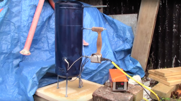
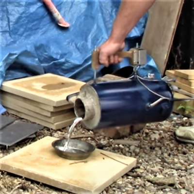 Sure, electric foundries lack some of the sex-appeal of gas- or even charcoal-fueled foundries, but by eschewing the open flames and shooting sparks, [Turbo Conquering Mega Eagle] was able to integrate the crucible into the foundry body and create what looks for all the world like a Thermos bottle for molten aluminum.