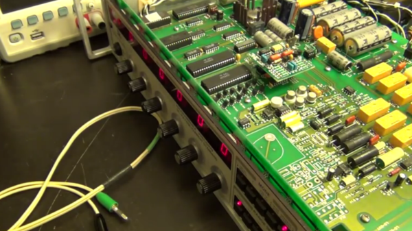
Precision standards are the pinnacle of test and measuring instrumentation. Well engineered, sure, but also beautifully built and a feast to look at, no matter how old they are. [Shahriar] at “The Signal Path” often gives us the skinny on such equipment. In the latest episode, we get a look inside a Valhalla 2701C Programmable Precision DC Voltage Standard.
Even by 1990 standards, it is a fairly basic instrument, capable of producing just DC Voltages from 100nV up to 1200V. But it is a reference standard, so the output is highly stable, accurate and precise. He snagged it from eBay on the cheap but transport seemed to have caused some damage. It would switch on and relays would click when he pressed buttons, but the 7-segment LED display was blank. Luckily, opening the top cover fixes that problem – just a loose connection between the front display and the main board. Examination also shows that adding a 120mA DC current range would require adding additional components on the main board so his hope of doing a quick firmware upgrade is short lived.
[Shahriar] takes the opportunity to walk us through the various sections of the well built unit. It’s apparently seen some repairs during it’s life. A few capacitors look changed, and a relay housing has seen damage from a soldering iron. The digital section is mainly the 6800 micro controller, an EPROM and a NVRAM, and it generates the PWM signals needed for producing the output voltages. A highly precise reference signal is essential for such equipment, and this one uses the LM299 with a “custom” suffix meaning it was specially screened and binned. He does a quick calibration run, but it’s obviously rushed and doesn’t produce stable results. But that could also be due to the low quality cables he used, or a number of other factors. Calibrating such equipment is a job demanding both time and patience.
While this may not knock your socks off. For that, check out this post where [Shahriar] does a tear down of the one million dollar Labmaster 10-100zi Oscilloscope, or this other one where he plays around with a half a million dollar oscilloscope you’ll probably never use, much less own.
Continue reading “Repair And Calibration Of Valhalla Programmable Precision Standard”

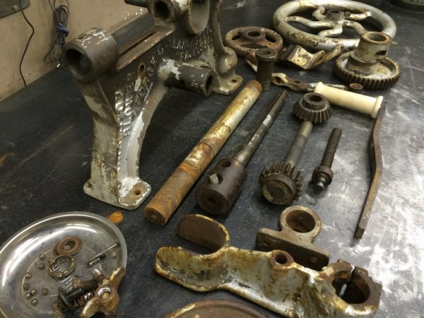
 There are three things that [Gord] has going for him. First off, the Champion Blower and Forge Co. built them to last. Second, he’s not really working on a deadline; the museum doesn’t need it back until May. And third, [Gord] has the tools he needs to do this right.


