Ceramic capacitors are pretty much the pixie dust of the electronics world. If you sprinkle enough of them on a circuit, everything will work. These ceramic capacitors aren’t the newest and latest technology, though: you can find them in radios from the 1930s, and they have one annoying property: their capacitance changes in relation to voltage.
This is a problem if you’re relying on ceramic caps in an RC filter or a power supply. What you need is a device that will graph capacitance against voltage, and [limpkin] is here to show you how to do it.
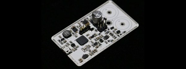
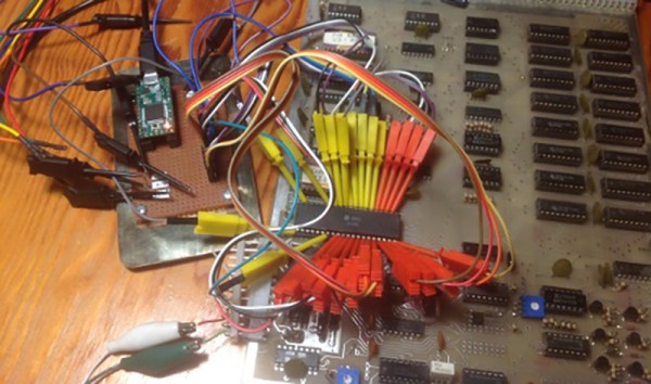
Of course capacitance is usually measured by timing how long it takes to charge and discharge a cap through an RC oscillator. This requires at least one known value – in this case a 0.1% resistor – by measuring the time it takes for this circuit to oscillate, an unknown capacitance can be calculated.
That’s all well and good, but how do you measure capacitance against a bias voltage? EDN comes to save the day with a simple circuit built around an op-amp. This op-amp is just a comparator, with the rest of the circuit providing a voltage directly proportional to the percentage of charge in the capacitor.
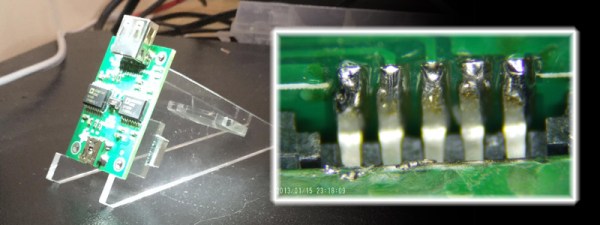
This little project is something [limpkin] has turned into a Kickstarter, and it’s something we’ve seen before. That said, measuring capacitance against a voltage isn’t something any ‘ol meter can do, and we’re glad [limpkin] could put together an easy to use tool that measures this phenomenon.
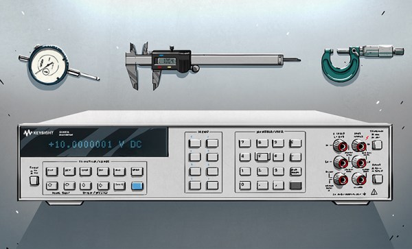
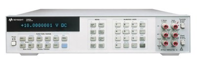 But what, you might ask, makes the 3458A such a significant and desirable instrument? It’s all in the digits. The 3458A is one of the few 8.5 digit multimeters available. It is therefore sensitive to microvolt deflections on 10 volt measurements. It is this ability to distinguished tiny changes on large signals that sets high precision multimeters apart. Imagine weighing an elephant and being able to count the number of flies that land on its back by the change in weight. The 3458A accomplishes a similar feat.