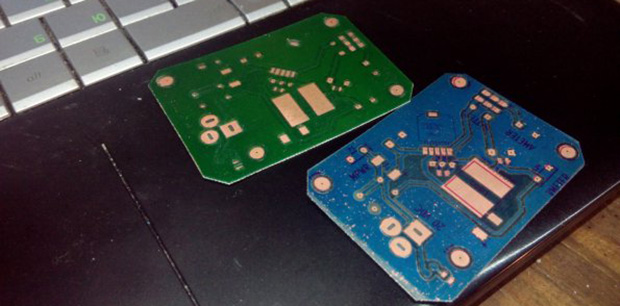
Thermocouple Vacuum Gauge Teardown

We don’t know how [Ben Krasnow] gets his hands on so much cool hardware. This time around is a bit of vintage tech: a thermocouple vacuum gauge.

The part seen above, and represented in the schematic, is the sensor side of things. This is interesting enough by itself. It has an air chamber with an electric heater element in it. When air is present it dissipates the heat, when under vacuum the heat builds and causes the thermocouple to generate some voltage on its connections.

Keep watching his presentation and things get a lot more interesting. The original unit used to measure the sensor is a throwback to the days when everything had sharp corners and if you were running with scissors you’d eventually teach yourself why that’s not such a good idea. The designers were rather cavalier with the presence of mains voltage, as it is barely separated from connections grounding the case itself.

Want to see some of the other cool equipment he’s got on hand? How about a CT scanner he built.

Continue reading “Thermocouple Vacuum Gauge Teardown”

Resistance Decade Box Using DIP Switches

resistance-decade-box

Here’s a simple piece of equipment which you’ll be proud to display on your electronics bench. It’s a resistance decade box. The concept has been around forever — it offers the ability to tune a wide range of resistance values just by adjusting the controls. We especially like the clean look of this one, and think the use of DIP switches is a nice touch.

Check out the toggle switch at the top. It lets you disconnect the resistance values from the output in order to test them with your meter. It may not seem like much, but fudging your switch settings could end up smoking your target project. The value of that feature isn’t lost on us.

The DIP switches are mounted to some Radio Shack breakout boards which work perfectly for hosting the resistors as well. This keeps the inside of the enclosure nice and tidy. The final touch is the printed face plate applied to the cover of the box.

Like we’ve said, this one is nice but our favorite is still this one that uses thumbwheel switches to dial in a value.

Making PCBs And Waffles

waffle

The toner transfer method of fabricating PCBs is a staple in every maker’s toolbox. Usually, tutorials for this method of making PCBs rely on a clothes iron or laminating machine. They work perfectly well, but with both of these methods (sans high-end laminators), you’re only heating one side of the board at a time, making perfect double-sided PCBs somewhat of a challenge.

[Mark] just came up with an interesting solution to this problem. A waffle iron PCB press. Technically, [Mark] is using his ‘grill and waffle baker’ as a two-sided griddle, with a few aluminum plates sandwiching the copper board for good thermal conduction.

After a whole lot of trial and error, [Mark] eventually got a good transfer onto a piece of copper clad board. Now that he has the process dialed in, it should be a snap to replicate his results with a new project and a new PCB design.

Arduino Oscilloscope At Five Megasamples Per Second

There’s no substitute for a proper oscilloscope on your electronics bench. But unfortunately we still don’t have one of our own. But we’ve got an Arduino board and paired with another IC it can sample an astonishing 5 million cycles per second.

[Bob Davis] has been working on an Arduino based oscillscope for a while now. He keep squeezing more and more performance out of it. A previous version hit 3 megasamples using an AD775 chip. When he added a FIFO buffer chip he was able to squeeze 10-25 megasamples out of it… wow! Unfortunately the output tended to be glitchy.

This version gets rid of the AD775 in favor of a CA3306. Both are analog-to-digital converters but the new circuit is less complex and more reliable. It uses just three capacitors and an external clock to support the IC. Take a look at the video below to see how it performs. He’s outputting a graph of the samples on a small LCD screen. The best part is that since the extra chip is doing the sampling this can be ported to your microcontroller of choice.

Continue reading “Arduino Oscilloscope At Five Megasamples Per Second”

Unlocking A Rigol Scope Once Again

Rigol scopes are finding their way onto the workbenches of makers the world over. There’s a reason for that – they’re so easily upgraded. With a simple software update, you can turn the 50 MHz Rigol o’scope into a model with 100 MHz of bandwidth. Design decisions in one model are sometimes carried over to different product lines, so eventually someone would figure out how to turn the 70 MHz DS2072 scope into the 200 MHz DS2202. A great mod that turns an $800 oscilloscope into one with the features of a $1600 scope.

There’s no internal modifications necessary for this mod; it works simply by sending a few engineering unlock codes to the scope over USB, a simple task that [Blair] implemented with a Raspberry Pi and a bit of Python code. The only fault of the hack is the scope resetting each time it’s powered off. This can, in fact, be accomplished with just about any microcontroller with a Python interpreter.

A fairly uninformative demo video is available below, or you could check out the EEVBlog thread where this mod was conceived here.

We here at Hackaday expect a small, cheap USB/microcontroller dongle thingy that automagically updates the DS2072 to show up in our inbox any day now. We thank whoever sends that in.

Continue reading “Unlocking A Rigol Scope Once Again”

The Definitive Guide To Solder Stencils

Yes, we’ve seen our share of tutorials for making solder paste stencils, but [Felix] hit it out of the park with this one. It’s the definitive guide to making solder stencils at home, with quality as good as you would find in any professionally made stencil.

The material for the stencils comes from the same source as so many other DIY solder stencils – aluminium cans. The interior plastic coating and the exterior paint job are both removed with heat, acetone, and patience. After laying out the cream layer of his board in a PDF file, [Felix] used a fairly interesting transfer medium to get the toner onto the aluminum; cheap vinyl shelving paper attached to a piece of paper apparently makes for an ideal surface to transfer toner.

After transfer, the board is etched with HCl and peroxide. [Felix] is getting some very good results with his method, including a few very fine pitch IC footprints. It’s just as good as a professionally made, laser cut stainless stencil, and you probably already have all the necessary ingredients lying around your house. That’s a win anytime.

Turning Grandpa’s O-scope Into A Clock

clock

Around 1960, [Aaron]’s grandfather decided to try his hand at a new career in electronics repair. It didn’t pan out, but before he gave up he built a beautiful Heathkit oscilloscope, a model OR-1. Grandpa’s electronics career never took off, but years later it would serve as the impetus for [Aaron]’s own career in electronics. Now [Aaron] has too many oscilloscopes, but still wanted a way to preserve his grandfather’s legacy. An oscilloclock was just the project to do that.

Of course to turn an oscilloscope into a clock requires some interesting control circuitry, and [Aaron] didn’t skimp on his build. He created a custom control board that is able to draw any shape on the CRT screen using just circles; squashing circles to draw a line, and cutting the beam entirely to slice a circle in half.

This isn’t [Aaron]’s first oscilloclock by a long shot. He previously created this amazing clock completely from scratch. Still, using Grandpa’s old tools is a great way to make this oscilloscope useful again, even if [Aaron] is already up to his gills in test equipment.