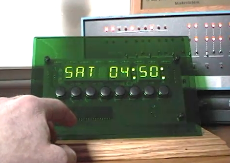
Over-engineered Clock Finds Purpose As RSS Reader

[Bob Alexander] admits that he over-engineered his clock, giving it eight control buttons, eight twelve-segment alpha-numeric display digits, a GPS module as a time source, and a beefy microcontroller to boot. But he’s found a way to get more for his money out of the device by adding RSS and weather features to it.

Since he’s using the PIC 18F4550 it’s a snap to add USB connectivity. From there he wrote a fantastic PC-side application for communicating with the display. Now he has the option of displaying time, RSS feeds, or weather by scrolling through the options with one of the buttons. Perhaps the best feature is the option to launch a browser on the PC and view the current story just by pressing a button on the display. Check out the two demos after the break; one shows the clock features and the other demonstrates the C# software.

Continue reading “Over-engineered Clock Finds Purpose As RSS Reader”

PIC Spectrum Analyzer Uses Fast Fourier Transform Routine

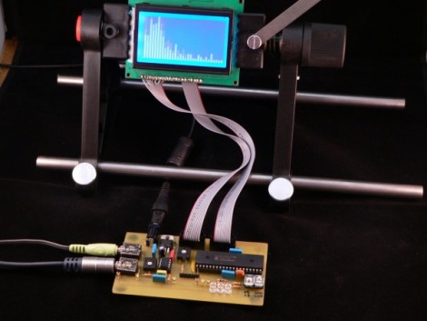
[Simon Inns] just rolled out his latest project, a PIC based spectrum analyzer. He’s using a Fast Fourier Transform routine crafted in C to run as efficiently as possible on the 8-bit chip. The video after the break shows that the results are quite pleasing, with just a bit of noticeable lag between the sound and the waveform representation on the graphic LCD. We found his notes about using an audio amplifier chip to be interesting. He utilizes the properties of an LM386 to move the input signals from a range of -0.5V to +0.5V into a very ADC friendly range of 0-5V.

Continue reading “PIC Spectrum Analyzer Uses Fast Fourier Transform Routine”

Bi-color LED Matrix Clock Uses Point-to-point Construction

[Daniel] wanted his child to stay in bed until a semi-decent time each morning. The problem is the kid doesn’t know how to read a clock, so [Daniel] built him a clock. Yeah, doesn’t make much sense to us either, but we’ve used our own shaky premises for projects so who are we do judge?

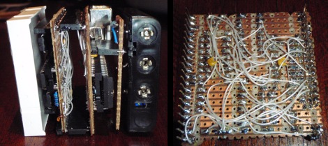
He used a bi-color 8×8 LED matrix as the clock display. What caught our eye is the point-to-point soldering he used for the three strip boards that make up the device. Note the use of a drill-bit to break the traces when needed. Each board has its own purpose; the matrix drive, the logic board, and the power board. A PIC 18F4550 lets [Daniel] control the clock via USB, and takes care of lighting up the hour as a red number when it’s time to sleep, and a green one when it’s okay to arise. There’s a flashing pixel for seconds, and a binary readout of minutes along the bottom.

We’ve asked [Daniel] to post a schematic and an image of the clock face when displaying the time. No word yet but we’ll keep our eye on it. In the mean-time, check out this clock that uses an RGB 8×8 LED matrix.

Car Computer Requires PIN For Ignition

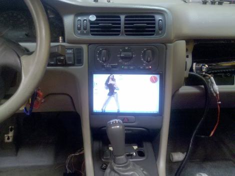
[Ben’s] added some nice goodies to his Volvo in the form of an in-dash computer. The system monitors two pressure sensors for boost and vacuum, as well as reading RPM, O2, and exhaust directly. All of this is tied into the touch interface running on an eeePC 900A. But our favorite feature is that the system requires you to enter a PIN to start the ignition. The forum post linked above is short on details so we asked [Ben] if he could tell us more. Join us after the break for a demonstration video as well as [Ben’s] rundown on the system.

Continue reading “Car Computer Requires PIN For Ignition”

PIC Based USB Input Devices

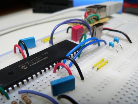
USB is convenient and that makes it desirable in many many projects. [Simon Inns] has the process down and is sharing it with his recent PIC based USB tutorial. Prompted by requests for help on the matter after having published a post about his Commodore 64 interface, he set out to detail the particulars when it comes to using the PIC 18F family as USB input devices. This example uses a PIC 18F4550 with the circuit built on a breadboard. There’s not much required here, an oscillator, a few passives, and a USB B connector. The magic really happens in the code. Take a look at this well-written guide and give it a try with your next project.

Don’t need USB? [Simon’s] game hack, the Ultimate Simon is always worth another look too.

PIC Powered AVR Programmer

[Texane] wrote in to let us know he has implemented AVR ISP programming using a PIC microcontroller. He wrote some code for an 18F4550 that uses the STK500 standard for In System Programming. This means that his hardware is compatible with AVRdude, the open source AVR programming software. There has long been an argument over the virtues of PIC versus AVR but we say why not both? If you have already honed your programming chops with PIC, you can build your own programmer and give the Atmel family a try.

The current implementation uses a serial port to connect the programmer to a computer. Keep your eye on this one as [texane] plans to add USB connectivity and has told us he will post schematics for the device as soon as that is complete.