You can have a lot of fun tinkering with the Raspberry Pi. But in addition to the low-cost hobby potential it is actually a great choice for serious data harvesting. This air quality monitor is a great example of that. The standalone package can be taped, screwed, bolted, or bungeed at the target location with a minimum of effort and will immediately start generating sample data.
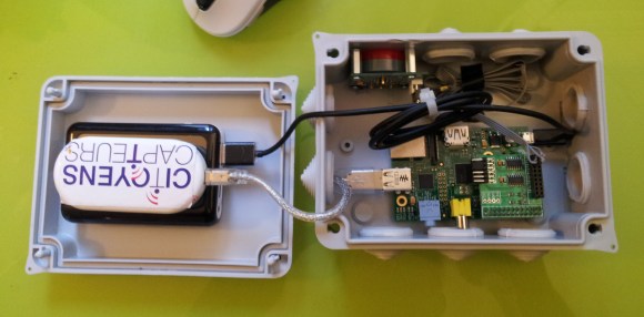
The enclosure is a weather proof electrical box. The RPi board is easy to spot mounted to the base of the case. On the lid there is an 8 Ah battery meant to top off an iPhone. It works perfectly as it provides a USB port and enough current to operate the Pi. On top of that battery is a 3G modem used to access the data remotely — although it can log to the SD card for collection at a later time if you’d rather not mess with a cell network.
Look closely at the GPIO header and you’ll notice that an ADC add-on board has been plugged in. This is used to take the readings from the gas sensor which is monitoring for air pollutants in Paris.