We get results! Well, sort of. You may recall that in this space last week we discussed Ford’s plans to exclude AM reception on the infotainment systems of certain of their cars starting in 2024. We decried the decision, not for the loss of the sweet, sweet content that AM stations tend to carry — although we always enjoyed “Traffic on the 8s” back in our dismal days of daily commuting — but rather as a safety concern, because AM radio can reach almost the entire US population with emergency information using just 75 stations. To our way of thinking, this makes AM radio critical infrastructure, and eliminating it from motor vehicles is likely to have unintended consequences. Now it seems like there’s some agreement with that position, as former administrators of FEMA (Federal Emergency Management Administration; and no, not FEDRA) have gotten together to warn about the dangers of deleting AM from cars. Manufacturers seem to be leaning into the excuse that EVs emit a lot of radio frequency interference, rendering static-sensitive AM receivers less useful than other, more profitable less susceptible modes, like digital satellite radio. That seems like a red herring to us, but then again, the most advanced infotainment option in any car we’ve ever owned is a CD player, so it’s hard for us to judge.
am radio36 Articles
Hackaday Links: March 12, 2023
With a long history of nearly universal hate for their products, you’d think printer manufacturers would by now have found ways to back off from the policies that only seem to keep aggravating customers. But rather than make it a financially wiser decision to throw out a printer and buy a new one than to buy new ink cartridges or toners, manufacturers keep coming up with new and devious ways to piss customers off. Case in point: Hewlett-Packard now seems to be bricking printers with third-party ink cartridges. Reports from users say that a new error message has popped up on screens of printers with non-HP cartridges installed warning that further use of the printer has been blocked. Previously, printers just warned about potential quality issues from non-HP consumables, but now they’re essentially bricked until you cough up the money for legit HP cartridges. Users who have contacted HP support say that they were told the change occurred because of a recent firmware update sent to the printer, so that’s comforting.
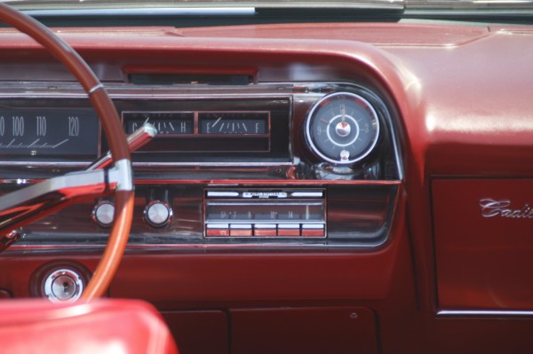
Ask Hackaday: Will Your 2030 Car Have AM Radio?
Car makers have been phasing out AM radios in their cars for quite some time. Let’s face it, there isn’t much on AM these days, and electric vehicles have been known to cause interference with AM radios. So why have them? For that matter, many aftermarket head units now don’t even have radios at all. They play digital media or stream Bluetooth from your phone. However, a U.S. Senator, Edward J. Markey, has started a letter-writing campaign to the major car makers urging them to retain the AM radio in their future vehicles.
So does that mean AM lives? Or will the car makers kill it off? The letter requests that the companies answer several questions, including if they plan to discontinue AM or FM radios in the near future and if they support digital broadcast radio.
Continue reading “Ask Hackaday: Will Your 2030 Car Have AM Radio?”
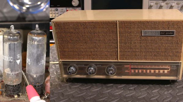
Busted 1960s Vacuum Tube Radio Sings Again
Restoring a vintage radio receiver has the potential to be a fun weekend project, but it pays to know what you’re up against. Especially in the case of vacuum tube electronics, running down gremlins in the circuits isn’t always a straightforward process (also, please mind the high voltage that is present in old vacuum tube equipment). [Mr Carlson] has a knack for getting old radios humming once again, and his repair of a 1960s General Electric barn find radio receiver is a thorough masterclass in vintage electronics servicing.
Seriously, if you’ve got a spare ninety minutes, the video (after the break) is a thorough and unabridged start-to-finish diagnosis and repair of a vintage radio, and an absolute must for anyone interested in doing the same. This barn find radio was certainly showing its age, and it wasn’t long before in-circuit testing found an open filament in one of several vacuum tubes, but the radio was still stubbornly silent. Further testing revealed that the IF transformers were out of spec, requiring servicing and alignment. After fine tuning both the IF and RF sections of the radio, things were definitely looking (and sounding) better.
Fine tuning the various components in the radio went a long way to living up to its “long range” claims, and by the end of the video, it’s almost impossible to find dead air on the AM dial of this radio. If you’ve never had to make fine adjustments to a receiver, especially of this vintage, this video has all the details you’ll need. With the board exposed, [Mr Carlson] also took care of some preventative maintenance, including replacing the original filter capacitor with newer components, as well as replacing the mains safety capacitor with an even safer modern alternative.
We can’t get enough of these restorations, so make sure to check out our detailed write-up of restoring a WWII aircraft radio.
Continue reading “Busted 1960s Vacuum Tube Radio Sings Again”
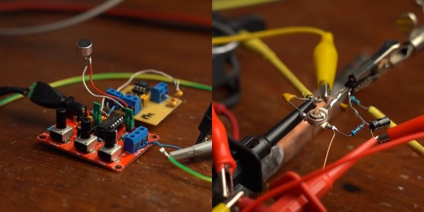
Some Of The Many Ways To Build AM Transmitters And Receivers
AM radios are relatively simple devices, and building one is a good way to start exploring the world of radio communications. [GreatScott] does exactly this in the video after the break, building both a transmitter and receiver.
At the most basic level, AM radio works by generating a carrier wave with an oscillator, and then modulating the amplitude with an audio signal. Around these parts, the venerable 555 timer is always brought up whenever things get to oscillating; so you’ll no doubt be happy to see [GreatScott] decided to give it a shot for his first experiments, testing two popular 555 transmitter circuits. One uses the control voltage pin to input the audio signal, while the other uses the reset pin. The CV-pin version worked slightly better, but it was still just barely possible to distinguish a voice over a standard commercial AM/FM receiver.
The next attempt was with a XR2206 function generator kit, which worked quite well when combined with a simple microphone amplifier circuit. But this time the receiving side was swapped out, as [GreatScott] built a basic circuit around a TA7642 AM amplifier/demodulator IC, with only six passive components and a hand-wound coil.
There is no shortage of ways to build AM radios, and we’ve covered quite a few over the years. Off course a 555 timer can also be used in a receiver, and building transmitters using only discrete components is quite simple, as demonstrated by the 10-minute transmitter and single transistor transmitter.
Continue reading “Some Of The Many Ways To Build AM Transmitters And Receivers”
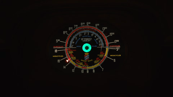
1938 Radio Has Awesome Dial
[Mr. Carlson] is truly an old radio surgeon. The evidence? He recently restored an 83-year-old DeForest radio by transplanting an identical chassis from another similar radio. The restoration is fun to watch, but the 7D832 radio dial looks amazing. The dial is very colorful and the wooden knobs and preset selector are beautiful. To seal the deal, the center of the dial has a magic eye tube, giving the radio a retro high tech look.
The donor chassis needed some work before the surgery. In addition, [Carlson] makes some improvements along the way. The radio showed signs of previous service work, which is not surprising after 83 years.
Listening To An IPhone With AM Radio
Electronic devices can be surprisingly leaky, often spraying out information for anyone close by to receive. [Docter Cube] has found another such leak, this time with the speakers in iPhones. While repairing an old AM radio and listening to a podcast on his iPhone, he discovered that the radio was receiving audio the from his iPhone when tuned to 950-970kHz.
[Docter Cube] states that he was able to receive the audio signal up to 20 feet away. A number of people responded to the tweet with video and test results from different phones. It appears that iPhones 7 to 10 are affected, and there is at least one report for a Motorola Android phone. The amplifier circuit of the speaker appears to be the most likely culprit, with some reports saying that the volume setting had a big impact. With the short range the security risk should be minor, although we would be interested to see the results of testing with higher gain antennas. It is also likely that the emission levels still fall within FCC Part 15 limits.


