Hackaday Links Column Banner

Hackaday Links: September 21, 2025

Remember AOL? For a lot of folks, America Online was their first ISP, the place where they got their first exposure to the Internet, or at least a highly curated version of it. Remembered by the cool kids mainly as the place that the normies used as their ISP and for the mark of shame an “@aol.com” email address bore, the company nevertheless became a media juggernaut, to the point that “AOL Time Warner” was a thing in the early 2000s. We’d have thought the company was long gone by now, but it turns out it’s still around and powerful enough of a brand that it’s being shopped around for $1.5 billion. We’d imagine a large part of that value comes from Yahoo!, which previous owner Verizon merged with AOL before selling most of the combined entity off in 2021, but either way, it’s not chump change.

For our part, the most memorable aspect of AOL was the endless number of CDs they stuffed into mailboxes in the 90s. There was barely a day that went by that one of those things didn’t cross your path, either through the mail or in free bins at store checkouts, or even inside magazines. They were everywhere, and unless you were tempted by the whole “You’ve got mail!” kitsch, they were utterly useless; they didn’t even make good coasters thanks to the hole in the middle. So most of the estimated 2 billion CDs just ended up in the trash, which got us thinking: How much plastic was that? A bit of poking around indicates that a CD contains about 15 grams of polycarbonate, so that’s something like 30,000 metric tonnes! To put that into perspective, the Great Pacific Garbage Patch is said to contain “only” around 80,000 metric tonnes of plastic. Clearly the patch isn’t 37% AOL CDs, but it still gives one pause to consider how many resources AOL put into marketing.

Continue reading “Hackaday Links: September 21, 2025”

Motorized Coil Tunes Your Ham Antenna On A Budget

When it comes to amateur radio, one size definitely does not fit all. That’s especially true with antennas, which need to be just the right size for the band you’re working, lest Very Bad Things happen to your expensive radio. That presents a problem for the ham who wants the option to work whichever band is active, and doubly so if portable operation is desired.

Of course, there are commercial solutions to this problem, but they tend to be expensive. Luckily [Øystein (LB8IJ)] seems to have found a way around that with this low-cost homebrew motorized antenna coil, which is compatible with the Yaesu Automatic Tuning Antenna System. ATAS is supported by several Yaesu transceivers, including the FT-891 which [Øystein] favors for field operations. ATAS sends signals up the feedline to a compatible antenna, which then moves a wiper along a coil to change the electrical length of the antenna, allowing it to resonate on the radio’s current frequency.

The video below details [Øystein]’s implementation of an ATAS-compatible tuning coil, mainly focusing on the mechanical and electrical aspects of the coil itself, which takes up most of the room inside a 50-mm diameter PVC tube. The bore of the air-core coil has a channel that guides a wiper, which moves along the length of the coil thanks to a motor-driven lead screw. [Øystein] put a lot of work into the wiper, to make it both mechanically and electrically robust. He also provides limit switches to make sure the mechanism isn’t over-driven.

There’s not much detail yet on how the control signals are detected, but a future video on that subject is promised. We’re looking forward to that, but in the meantime, the second video below shows [Øystein] using the tuner in the field, with great results.

Continue reading “Motorized Coil Tunes Your Ham Antenna On A Budget”

Junk Box Build Helps Hams With SDR

SDRs have been a game changer for radio hobbyists, but for ham radio applications, they often need a little help. That’s especially true of SDR dongles, which don’t have a lot of selectivity in the HF bands. But they’re so darn cheap and fun to play with, what’s a ham to do?

[VK3YE] has an answer, in the form of this homebrew software-defined radio (SDR) helper. It’s got a few features that make using a dongle like the RTL-SDR on the HF bands a little easier and a bit more pleasant. Construction is dead simple and based on what was in the junk bin and includes a potentiometer for attenuating stronger signals, a high-pass filter to tamp down stronger medium-wave broadcast stations, and a series-tuned LC circuit for each of the HF bands to provide some needed selectivity. Everything is wired together ugly-style in a metal enclosure, with a little jiggering needed to isolate the variable capacitor from ground.

The last two-thirds of the video below shows the helper in use on everything from the 11-meter (CB) band down to the AM bands. This would be a great addition to any ham’s SDR toolkit.

Continue reading “Junk Box Build Helps Hams With SDR”

Schooling ChatGPT On Antenna Theory Misconceptions

We’re not very far into the AI revolution at this point, but we’re far enough to know not to trust AI implicitly. If you accept what ChatGPT or any of the other AI chatbots have to say at face value, you might just embarrass yourself. Or worse, you might make a mistake designing your next antenna.

We’ll explain. [Gregg Messenger (VE6WO)] asked a seemingly simple question about antenna theory: Does an impedance mismatch between the antenna and a coaxial feedline result in common-mode current on the coax shield? It’s an important practical matter, as any ham who has had the painful experience of “RF in the shack” can tell you. They also will likely tell you that common-mode current on the shield is caused by an unbalanced antenna system, not an impedance mismatch. But when [Gregg] asked Google Gemini and ChatGPT that question, the answer came back that impedance mismatch can cause current flow on the shield. So who’s right?

In the first video below, [Gregg] built a simulated ham shack using a 100-MHz signal generator and a length of coaxial feedline. Using a toroidal ferrite core with a couple of turns of magnet wire and a capacitor as a current probe for his oscilloscope, he was unable to find a trace of the signal on the shield even if the feedline was unterminated, which produces the impedance mismatch that the chatbots thought would spell doom. To bring the point home, [Gregg] created another test setup in the second video, this time using a pair of telescoping whip antennas to stand in for a dipole antenna. With the coax connected directly to the dipole, which creates an unbalanced system, he measured a current on the feedline, which got worse when he further unbalanced the system by removing one of the legs. Adding a balun between the feedline and the antenna, which shifts the phase on each leg of the antenna 180° apart, cured the problem.

We found these demonstrations quite useful. It’s always good to see someone taking a chatbot to task over myths and common misperceptions. We look into baluns now and again. Or even ununs.

Continue reading “Schooling ChatGPT On Antenna Theory Misconceptions”

Ferrites Versus Ethernet In The Ham Shack

For as useful as computers are in the modern ham shack, they also tend to be a strong source of unwanted radio frequency interference. Common wisdom says applying a few ferrite beads to things like Ethernet cables will help, but does that really work?

It surely appears to, for the most part at least, according to experiments done by [Ham Radio DX]. With a particular interest in lowering the noise floor for operations in the 2-meter band, his test setup consisted of a NanoVNA and a simple chunk of wire standing in for the twisted-pair conductors inside an Ethernet cable. The NanoVNA was set to sweep across the entire HF band and up into the VHF; various styles of ferrite were then added to the conductor and the frequency response observed. Simply clamping a single ferrite on the wire helped a little, with marginal improvement seen by adding one or two more ferrites. A much more dramatic improvement was seen by looping the conductor back through the ferrite for an additional turn, with diminishing returns at higher frequencies as more turns were added. The best performance seemed to come from two ferrites with two turns each, which gave 17 dB of suppression across the tested bandwidth.

The question then becomes: How do the ferrites affect Ethernet performance? [Ham Radio DX] tested that too, and it looks like good news there. Using a 30-meter-long Cat 5 cable and testing file transfer speed with iPerf, he found no measurable effect on throughput no matter what ferrites he added to the cable. In fact, some ferrites actually seemed to boost the file transfer speed slightly.

Ferrite beads for RFI suppression are nothing new, of course, but it’s nice to see a real-world test that tells you both how and where to apply them. The fact that you won’t be borking your connection is nice to know, too. Then again, maybe it’s not your Ethernet that’s causing the problem, in which case maybe you’ll need a little help from a thunderstorm to track down the issue. Continue reading “Ferrites Versus Ethernet In The Ham Shack”

Off-Grid Radio Also Repairable Off-Grid

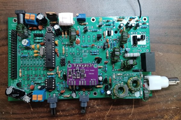
Low-power radios, often referred to in the amateur radio community as QRP radios, have experienced a resurgence in popularity lately. Blame it on certain parts of the hobby become more popular, like Parks on the Air (POTA) or Summits on the Air (SOTA). These are events where a radio operator operates off-grid at remote parks or mountaintops. These QRP rigs are a practical and portable way to make contacts. You would think that a five- or ten-watt rig running on batteries would be simple. Surprisingly, they can be enormously complex and expensive. That’s why [Dr. Daniel Marks] built the RFBitBanger, a QRP radio designed to not only be usable off-grid but to be built and maintained off-grid as well.

The radio accomplishes this goal by being built out of as many standard off-the-shelf components as possible. It eschews modern surface-mount components in favor of the much more accessible through-hole parts, including the ATMEGA328P at the center of the build. A PCB design is also available, but it can be built on perf board nearly as easily. The radio supports any mode a QRP operator might use, including CW, SSB, RTTY, and a new mode designed explicitly for this radio called SCAMP which is a low bandwidth, low SNR digital mode built into the Arduino-based firmware. It’s a single-band radio, but any band between 20 and 80 meters can be selected with pluggable filters.

As far as bomb-proof radios go, we can’t imagine a better way to live out an apocalypse than with a radio like this. As long as there’s a well-stocked parts drawer around, this radio could theoretically reach around the world without worrying about warranty claims, expensive parts, or even a company going out of business or not stocking parts for old radios anymore. There’s also more information about this build at the Open Research Institute for those interested. And, if you’re wondering how useful any radio could be using only five watts of transmitter power, take a look at this in-depth look at QRP radio operation.

Thanks to [Stephen Walters] for the tip.

Amateur Estimates Of Venusian Day Using Arecibo Data

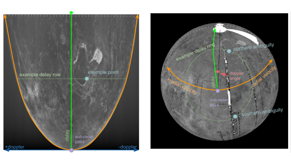
[Nathaniel Fairfield] aka [thandal] was curious about the actual rotation and axis tilt of Venus. He decided to spin up at GitHub Python repository to study the issue further, as one does. The scientific literature shows a wide range of estimates and variations for the planet’s rotation and axis tilt. He wondered if the real answer might be found in a publicly available set of uncalibrated delay-doppler images of Venus. These data were collected by the former Arecibo Observatory in Puerto Rico from 1988 through 2020.  [Thanda] observed that the planet’s rotation appears to be speeding up slightly, and furthermore, his estimates of the orbital axis were within 0.01 degrees of the International Astronomical Union’s (IAU) values. [Note: Venus is a bit confusing — one planetary rotation, 243 Earth days, is longer than its year, 225 Earth days].

Estimations of Venusian Orbital Period, [Thandal] Estimates in Green
Aligning and calibrating the raw data was no trivial task. You have to consider the radar’s (Earth’s) position and time, as well as Venus. Complicating the math even more, some times the radar was operated in a bistatic mode, with the Green Bank Telescope in West Virginia being the receiver.

There’s a lot of interesting signal processing going on here. The Doppler-delay data consists of images that are 8091×8092 array of complex values, has to be mapped onto the Venus geoid.  Then by using various surface features, one can compare their positions vs time and obtain an estimate of rotational speed and tilt. If these kinds of calculations interest you, be sure to check out [Thandal]’s summary report, and also take note of the poliastro Python astrodynamics library. Why is this important? One reason to better plan future missions.