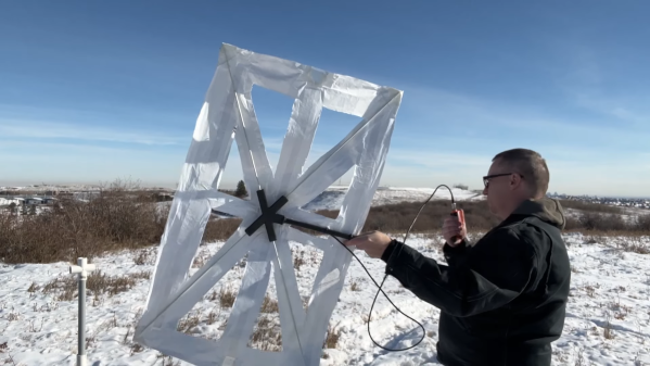
Generally, the biggest problem a new ham radio operator will come across when starting out on the high frequency (HF) bands is finding physical space for the antennas. For a quick example, a dipole antenna for the 20 m band will need around 10 m of wire, and the lower frequencies like 80 m need about four times as much linear space. But if you’re willing to trade a large space requirement for a high voltage hazard instead, a magnetic loop antenna might be just the ticket.
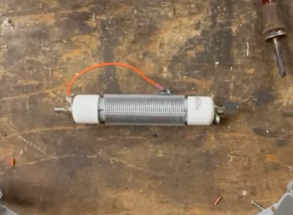
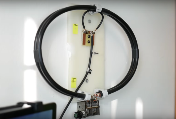
Loop antennas like these are typically used only for receiving, but in a pinch they can be used to transmit as well. To tune the antennas, which are much shorter than a standard vertical or dipole, a capacitor is soldered onto the ends, which electrically lengthens the antenna. [OM0ET] is using two loops of coax cable for the antenna, with each end soldered to one half of a dual variable capacitor which allows this antenna to tune from the 30 m bands to the 10 m bands, although he is using it mostly for WSPR on 20 m. His project also includes the use of an openWSPR module, meaning that he doesn’t have to dedicate an entire computer to run this mode.
The main downsides of antennas like these is that they are not omnidirectional, are not particularly good at transmitting, and develop a significantly high voltage across the capacitor as this similar mag loop antenna project demonstrated. But for those with extreme limitations on space or who, like [OM0ET] want a simple, small setup for running low-power applications like WSPR they can really excel. In fact, WSPR is a great mode for getting on the air at an absolute minimum of cost.