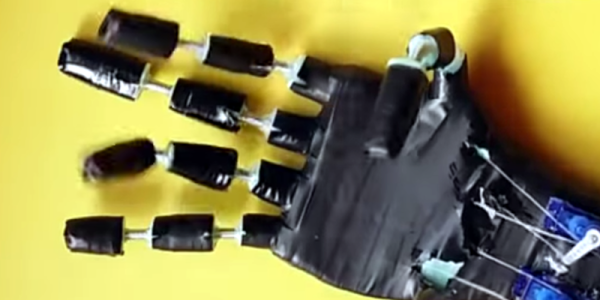
Arduino + Geometry + Bicycle = Speedometer

It is pretty easy to go to a big box store and get a digital speedometer for your bike. Not only is that no fun, but the little digital display isn’t going to win you any hacker cred. [AlexGyver] has the answer. Using an Arduino and a servo he built a classic needle speedometer for his bike. It also has a digital display and uses a hall effect sensor to pick up the wheel speed. You can see a video of the project below.

[Alex] talks about the geometry involved, in case your high school math is well into your rear view mirror. The circumference of the wheel is the distance you’ll travel in one revolution. If you know the distance and you know the time, you know the speed and the rest is just conversions to get a numerical speed into an angle on the servo motor. The code is out on GitHub.

Continue reading “Arduino + Geometry + Bicycle = Speedometer”

Hull Pixel Bot, A Mobile Pixel

There are many designs for little two-wheeled robots available to download for constructors with an interest in simple robotics. You might even think there are so many that there could not possibly be room for another, but that has not deterred [Rob Miles]. He’s created HullPixelBot, a platform for a mobile pixel as well as for simple robotic experimentation.

So what makes HullPixelBot more than just Yet Another Arduino Powered Robot? For a start, it’s extremely well designed, and has a budget of less than £10 ($12.50). But the real reason to take notice lies in the comprehensive software, which packs in a language interpreter and MQTT endpoint for talking to an Azure IoT hub. This is much more than a simple Arduino bot on which you must craft your own sketches, instead, it is a platform for which the Arduino bot is merely the carrier.

The project has had quite a while to mature since its initial release, and now has the option of a single pixel or a ring of pixels. The eventual aim is to use swarms of networked HullPixelBots to create large autonomous moving pixel displays, containing more than a hundred individual pixels.

There is an early video of some PixelBots in action which we’ve placed below the break, but it serves more as eye candy than anything else. If you have a spare ten quid, download and print yourself a chassis, install Arduino and motors, and have a go yourself!

Continue reading “Hull Pixel Bot, A Mobile Pixel”

A Command-Line Stepper Library With All The Frills

When you already know exactly where and how you’d like your motor to behave, a code-compile-flash-run-debug cycle can work just fine. But if you want to play around with a stepper motor, there’s nothing like a live interface. [BrendaEM]’s RDL is a generic stepper motor driver environment that you can flash into an Arduino. RDL talks to your computer or cell phone over serial, and can command a stepper-driver IC to move the motor in three modes: rotary, divisions of a circle, and linear. (Hence the acronumical name.) Best of all, the entire system is interactive. Have a peek at the video below.

The software has quite a range of capabilities. Typing “?” gets you a list of commands, typing “@” tells you where the motor thinks it is, and “h” moves the motor back to its home position. Rotating by turns, degrees, or to a particular position are simple. It can also read from an analog joystick, which will control the rotation speed forward and backward in real time.

Division mode carves the pie up into a number of slices, and the motor spins to these particular locations. Twelve, or sixty, divisions gives you a clock, for instance. Acceleration and deceleration profiles are built in, but tweakable. You can change microstepping on the fly, and tweak many parameters of the drive, and then save all of the results to EEPROM. If you’re playing around with a new motor, and don’t know how quickly it can accelerate, or what speeds it’s capable of, nothing beats playing around with it interactively.

Continue reading “A Command-Line Stepper Library With All The Frills”

See The Weather At A Glance With This WiFi Wall Mounted Display

Whether you’re lodged in an apartment with a poor view of the sky like [Becky Stern] or are looking for an at-a-glance report of the current weather, you might consider this minimalist weather display instead of checking your computer or your phone every time you’re headed out the door.

The first order of business was to set up her Feather Huzzah ESP8266 module. [Becky] started with a blink test to ensure it was working properly. Once that was out of the way, she moved on to installing a few libraries. Temperature data fetched by an IFTTT feed is displayed on a seven-segment display, while additional feeds separately retrieve information for each basic weather type: sunny, overcast, rain, snow.

All it took to create the sleek display effect was a few pieces of cardboard inside a shadow box frame, a sheet of paper as a diffuser, and twelve Neopixel RGB LEDs hidden inside. Trimming and securing everything in place as well as notching out the back of the frame for the power cable finished the assembly. Check out the build video after the break.

Continue reading “See The Weather At A Glance With This WiFi Wall Mounted Display”

Raiders Of The Lost OS: Reclaiming A Piece Of Polish IT History

In today’s digital era, we almost take for granted that all our information is saved and backed up, be it on our local drives or in the cloud — whether automatically, manually, or via some other service.  For information from decades past, that isn’t always the case, and recovery can be a dicey process.  Despite the tricky challenges, the team at [Museo dell’Informatica Funzionante] and [mera400.pl], as well as researchers and scientists from various museums, institutions, and more all came together in the attempt to recover the Polish CROOK operating system believed to be stored on five magnetic tapes.

MEERA-400 Tape Recovery 1

Originally stored at the Warsaw Museum of Technology, the tapes were ideally preserved, but — despite some preliminary test prep — the museum’s tape reader kept hanging at the 800 BPI NRZI encoded header, even though the rest of the tape was 1600 BPI phase encoding. Some head scratching later, the team decided to crack open their Qualstar 1052 tape reader and attempt to read the data directly off the circuits themselves!!

Continue reading “Raiders Of The Lost OS: Reclaiming A Piece Of Polish IT History”

The Best Of Both Worlds: Arduino + 555 Should Confuse Commenters

Hardly a week goes by that some Hackaday post doesn’t elicit one of the following comments:

That’s stupid! Why use an Arduino when you could do the same thing with a 555?

And:

That’s stupid! Why use a bunch of parts when you can use an Arduino?

However, we rarely see those two comments on the same post. Until now. [ZHut] managed to bring these two worlds together by presenting how to make an Arduino blink an LED in conjunction with a 555 timer. We know, we know. It is hard to decide how to comment about this. You can consider it while you watch the video, below.

Continue reading “The Best Of Both Worlds: Arduino + 555 Should Confuse Commenters”

Making A Mega LED Desk

Few things beat a sturdy, home-built desk — especially when it’s jam-packed with over 1200 WS2812 LEDs.

[nolobot] and his bother struggled with setting up and squaring-off the t-slotted, extruded aluminium frame which makes up the desk. He recommends practicing with a smaller frame for anyone else attempting a similar build. The surface of the desk has a few inches between the polycarbonate top and the 1/4″ plywood painted black serving as the substrate for the LEDs. Those LEDs come in strip form but still required several hundred solders, and wiring headaches in an attempt to make future upgrades manageable. Dozens of support bolts with adjustable feet support the desk surface throughout. These all had to be individually adjusted and can be made out if you look closely at the demo videos.

An Arduino Mega controls the LEDs with the help of the FastLED library. Custom code was necessary because one of the major issues [nolobot] faced was the power draw. 1200 LEDs at 5V draw quite a bit of current, so the LEDs were coded to peak at about 50% brightness. The matrix was split into different banks, while also limiting the 40A PSU to only 15A.

Continue reading “Making A Mega LED Desk”